background image

Notes, cautions, and warnings

NOTE:

 A NOTE indicates important information that helps you make better use of your product.

CAUTION:

 A CAUTION indicates either potential damage to hardware or loss of data and tells you how to avoid

the problem.

WARNING:

 A WARNING indicates a potential for property damage, personal injury, or death.

© 2021 Dell Inc. or its subsidiaries. All rights reserved. Dell, EMC, and other trademarks are trademarks of Dell Inc. or its subsidiaries. Other
trademarks may be trademarks of their respective owners.

Summary of Contents for P106F

Page 1: ...Vostro 15 5510 Service Manual Regulatory Model P106F Regulatory Type P106F001 October 2021 Rev A01 ...

Page 2: ...ential damage to hardware or loss of data and tells you how to avoid the problem WARNING A WARNING indicates a potential for property damage personal injury or death 2021 Dell Inc or its subsidiaries All rights reserved Dell EMC and other trademarks are trademarks of Dell Inc or its subsidiaries Other trademarks may be trademarks of their respective owners ...

Page 3: ...tery cable 21 Memory 22 Removing the memory module 22 Installing the memory module 23 Solid state drive M 2 slot one 25 Removing the 2230 solid state drive from M 2 slot one 25 Installing the 2230 solid state drive in M 2 slot one 25 Removing the 2280 solid state drive from M 2 slot one 26 Installing the 2280 solid state drive in M 2 slot one 27 Installing the solid state drive mounting bracket on...

Page 4: ...3 Removing the power adapter port 53 Installing the power adapter port 54 System board 55 Removing the system board 55 Installing the system board 58 Palm rest and keyboard assembly 62 Removing the palm rest and keyboard assembly 62 Installing the palm rest and keyboard assembly 63 Chapter 3 Drivers and downloads 65 Downloading the drivers 65 Chapter 4 System setup 66 BIOS overview 66 Entering BIO...

Page 5: ...portAssist Pre Boot System Performance Check 81 System diagnostic lights 81 Recovering the operating system 83 Updating the BIOS using the USB drive in Windows 83 Updating the BIOS in Windows 83 Backup media and recovery options 84 WiFi power cycle 84 Drain residual flea power perform hard reset 84 Chapter 6 Getting help and contacting Dell 85 Contents 5 ...

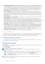
Page 6: ...d by Dell is not covered by your warranty See the safety instructions that is shipped with the product or at www dell com regulatory_compliance CAUTION Before touching anything inside your computer ground yourself by touching an unpainted metal surface such as the metal at the back of the computer While you work periodically touch an unpainted metal surface to dissipate static electricity which co...

Page 7: ...ailures means that most of the time when damage occurs it is not immediately recognizable The DIMM receives a static shock but the tracing is merely weakened and does not immediately produce outward symptoms related to the damage The weakened trace may take weeks or months to melt and in the meantime may cause degradation of memory integrity intermittent memory errors etc The more difficult type o...

Page 8: ...meters away from sensitive parts before physically handling any hardware components ESD Packaging All ESD sensitive devices must be shipped and received in static safe packaging Metal static shielded bags are preferred However you should always return the damaged part using the same ESD bag and packaging that the new part arrived in The ESD bag should be folded over and taped shut and all the same...

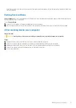
Page 9: ... on the computer Your computer will automatically return to normal functioning mode After working inside your computer About this task CAUTION Leaving stray or loose screws inside your computer may severely damage your computer Steps 1 Replace all screws and ensure that no stray screws remain inside your computer 2 Connect any external devices peripherals or cables you removed before working on yo...

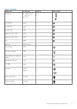
Page 10: ...ter port System board Palm rest and keyboard assembly Recommended tools The procedures in this document may require the following tools Phillips screwdriver 0 Plastic scribe Screw list NOTE When removing screws from a component it is recommended to note the screw type the quantity of screws and then place them in a screw storage box This is to ensure that the correct number of screws and correct s...

Page 11: ...x3 1 Solid state drive Slot 1 M2x3 1 Solid state drive Slot 2 M2x3 1 Fan M2x3 2 Heat sink Captive screws 4 System board M2x2 3 USB Type C bracket M2x4 2 Power button with fingerprint reader M2x3 1 Network port bracket M2x5 2 I O board M2x2 1 Touchpad M1 6x2 M2x1 8 3 2 Power adapter port M2 5x4 5 3 Display assembly M2 5x4 5 6 Removing and installing components 11 ...

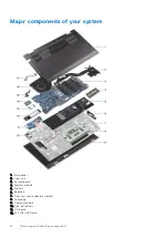
Page 12: ...1 Base cover 2 Heat sink 3 System board 4 Memory module 5 Battery 6 Speakers 7 Palm rest and keyboard assembly 8 Touchpad 9 Display assembly 10 Coin cell battery 11 I O board 12 M 2 2280 SSD card 12 Removing and installing components ...

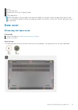
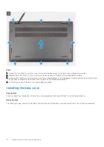
Page 13: ...available according to warranty coverages purchased by the customer Contact your Dell sales representative for purchase options Base cover Removing the base cover Prerequisites 1 Follow the procedure in Before working inside your computer 2 Enter Service Mode About this task The following images indicate the location of the base cover and provide a visual representation of the removal procedure Re...

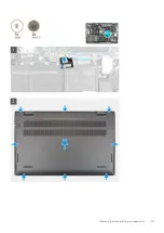
Page 14: ...base cover and continue to work on the sides to release the base cover from the palm rest and keyboard assembly 4 Lift the base cover off the palm rest and keyboard assembly Installing the base cover Prerequisites If you are replacing a component remove the existing component before performing the installation procedure About this task The following images indicate the location of the base cover a...

Page 15: ...Removing and installing components 15 ...

Page 16: ...n handling Lithium ion batteries Discharge the battery completely before removing it Disconnect the AC power adapter from the system and operate the computer solely on battery power the battery is fully discharged when the computer no longer turns on when the power button is pressed Do not crush drop mutilate or penetrate the battery with foreign objects Do not expose the battery to high temperatu...

Page 17: ...he 3 cell battery Prerequisites 1 Follow the procedure in Before working inside your computer 2 Remove the base cover About this task The following image indicates the location of the 3 cell 41 Wh battery and provides a visual representation of the removal procedure Steps 1 Peel the tape that secures the battery cable to the system board 2 Disconnect the battery cable from the system board 3 Remov...

Page 18: ...hat secure the 3 cell battery to the palm rest and keyboard assembly 4 Connect the battery cable to the system board 5 Adhere the tape that secures the battery cable to the system board Next steps 1 Install the base cover 2 Follow the procedure in After working on your computer Removing the 4 cell battery Prerequisites 1 Follow the procedure in Before working inside your computer 2 Remove the base...

Page 19: ... Lift the 4 cell battery along with its cable off the palm rest and keyboard assembly Installing the 4 cell battery Prerequisites If you are replacing a component remove the existing component before performing the installation procedure About this task The following image indicates the location of the 4 cell 54 Wh battery and provides a visual representation of the installation procedure Removing...

Page 20: ...Next steps 1 Install the base cover 2 Follow the procedure in After working on your computer Battery cable Removing the battery cable Prerequisites 1 Follow the procedure in Before working inside your computer 2 Remove the base cover 3 Remove the 3 cell battery or 4 cell battery whichever applicable NOTE If battery is disconnected from system board for service then there is a delay during system b...

Page 21: ...he battery cable off the battery Installing the battery cable Prerequisites If you are replacing a component remove the existing component before performing the installation procedure About this task The following image indicates the location of the battery cable and provides a visual representation of the installation procedure Removing and installing components 21 ...

Page 22: ...ery whichever applicable 2 Install the base cover 3 Follow the procedure in After working on your computer Memory Removing the memory module Prerequisites 1 Follow the procedure in Before working inside your computer 2 Enter Service Mode 3 Remove the base cover About this task The following images indicate the location of the memory module and provide a visual representation of the removal procedu...

Page 23: ...NOTE Repeat step 1 to step 3 to remove any other memory modules installed in your computer Installing the memory module Prerequisites If you are replacing a component remove the existing component before performing the installation procedure About this task The following image indicates the location of the memory module and provides a visual representation of the installation procedure Removing an...

Page 24: ...memory module slot 4 Press the memory module down until it clicks into place NOTE If you do not hear the click remove the memory module and reinstall it NOTE Repeat step 1 to step 4 to install any other memory modules in your computer Next steps 1 Install the base cover 2 Exit Service Mode 3 Follow the procedure in After working inside your computer 24 Removing and installing components ...

Page 25: ...or a 2280 solid state drive in M 2 slot one NOTE This procedure applies only to computers shipped with a 2230 solid state drive installed in M 2 slot one The following image indicates the location of the 2230 solid state drive that is installed in M 2 slot one and provides a visual representation of the removal procedure Steps 1 Remove the screw M2x3 that secures the 2230 solid state drive to the ...

Page 26: ...tallation procedure Steps 1 Align the notch on the 2230 solid state drive with the tab on the solid state drive slot 2 Slide the 2230 solid state drive firmly into the solid state drive slot at an angle 3 Align the screw hole on the solid state drive with the screw hole on the palm rest and keyboard assembly 4 Replace the screw M2x3 that secures the 2230 solid state drive to the palm rest and keyb...

Page 27: ...tate drive off the M 2 solid state drive slot one on the system board Installing the 2280 solid state drive in M 2 slot one Prerequisites If you are replacing a component remove the existing component before performing the installation procedure About this task NOTE Solid state drives are fragile Exercise care when handling the solid state drive NOTE Depending on the configuration ordered the comp...

Page 28: ...ith the screw hole on the palm rest and keyboard assembly 4 Replace the screw M2x3 that secures the 2280 solid state drive to the palm rest and keyboard assembly Next steps 1 Install the base cover 2 Exit Service Mode 3 Follow the procedure in After working inside your computer Installing the solid state drive mounting bracket on M 2 slot one About this task The following image provides a visual r...

Page 29: ...bracket slot on the palm rest and keyboard assembly 2 Rotate the solid state drive mounting bracket to 180 degrees 3 Slide the solid state mounting bracket into the mounting slot on the palm rest and keyboard assembly 4 Install the 2230 solid state drive or 2280 solid state drive whichever applicable Solid state drive M 2 slot two Removing the 2230 solid state drive from M 2 slot two Prerequisites...

Page 30: ...ise care when handling the solid state drive NOTE To avoid data loss do not remove the solid state drive while the computer is in sleep or on state 2 Enter Service Mode 3 Remove the base cover About this task The following image indicates the location of the 2230 solid state drive that is installed in M 2 slot two and provides a visual representation of the removal procedure 30 Removing and instal...

Page 31: ...lacing a component remove the existing component before performing the installation procedure About this task NOTE Solid state drives are fragile Exercise care when handling the solid state drive NOTE M 2 slot two supports only 2230 solid state drive NOTE This procedure applies only to computers shipped with a 2230 solid state drive installed in M 2 slot two The following image indicates the locat...

Page 32: ...solid state drive 4 Align the screw hole on the solid state drive thermal shield with the screw hole on the palm rest and keyboard assembly 5 Replace the screw M2x3 that secures the solid state drive thermal shield and solid state drive to the palm rest and keyboard assembly Next steps 1 Install the base cover 2 Exit Service Mode 3 Follow the procedure in After working inside your computer 32 Remo...

Page 33: ...location of the wireless card and provide a visual representation of the removal procedure Steps 1 Remove the screw M2x3 that secures the wireless card bracket to the wireless card and system board 2 Remove the wireless card bracket from the wireless card 3 Disconnect the antenna cables from the wireless card 4 Slide and remove the wireless card from the wireless card slot Removing and installing ...

Page 34: ...ides a visual representation of the installation procedure Steps 1 Connect the antenna cables to the wireless card The following table provides the antenna cable color scheme for the wireless card that is supported by your computer Table 2 Antenna cable color scheme Connectors on the wireless card Antenna cable color Silkscreen marking Main White MAIN white triangle Auxiliary Black AUX black trian...

Page 35: ...nd the system board Next steps 1 Install the base cover 2 Exit Service Mode 3 Follow the procedure in After working inside your computer Fan Removing the fan Prerequisites 1 Follow the procedure in Before working inside your computer 2 Enter Service Mode 3 Remove the base cover About this task The following images indicate the location of the fan and provide a visual representation of the removal ...

Page 36: ...on of the fan and provides a visual representation of the installation procedure Steps 1 Using the alignment posts place the fan on the palm rest and keyboard assembly 2 Replace the two M2x3 screws to secure the fan to the palm rest and keyboard assembly 3 Connect the fan cable to the system board Next steps 1 Install the base cover 2 Exit Service Mode 3 Follow the procedure in After working insid...

Page 37: ...de 3 Remove the base cover About this task The following images indicate the location of the coin cell battery and provide a visual representation of the removal procedure Steps 1 Disconnect the coin cell battery cable from the I O board 2 Using the flat end of a plastic scribe peel the coin cell battery from the palm rest and keyboard assembly Installing the coin cell battery Prerequisites If you...

Page 38: ...llow the procedure in After working inside your computer Heat sink Removing the heatsink Prerequisites 1 Follow the procedure in Before working inside your computer CAUTION For maximum cooling of the processor do not touch the heat transfer areas on the heat sink The oils in your skin can reduce the heat transfer capability of the thermal grease NOTE The heat sink may become hot during normal oper...

Page 39: ...k Prerequisites If you are replacing a component remove the existing component before performing the installation procedure CAUTION Incorrect alignment of the heat sink can damage the system board and processor NOTE If either the system board or the heat sink is replaced use the thermal pad paste provided in the kit to ensure that thermal conductivity is achieved About this task The following imag...

Page 40: ...cover 2 Exit Service Mode 3 Follow the procedure in After working inside your computer Network port bracket Removing the network port bracket Prerequisites 1 Follow the procedure in Before working inside your computer 2 Enter Service Mode 3 Remove the base cover About this task The following image s indicate the location of the network port bracket and provide a visual representation of the remova...

Page 41: ...talling the network port bracket Prerequisites If you are replacing a component remove the existing component before performing the installation process About this task The following image s indicate the location of the network port bracket and provide a visual representation of the installation procedure Removing and installing components 41 ...

Page 42: ...base cover 2 Exit Service Mode 3 Follow the procedure in After working inside your computer I O board Removing the I O board Prerequisites 1 Follow the procedure in Before working inside your computer 2 Enter Service Mode 3 Remove the base cover 4 Remove the network port bracket About this task The following images indicate the location of the I O board and provide a visual representation of the r...

Page 43: ...able to the I O board 6 Open the latch and disconnect the I O board cable from the I O board 7 Remove the screw M2x2 that secures the I O board to the palm rest and keyboard assembly 8 Lift the I O board off the palm rest and keyboard assembly Installing the I O board Prerequisites If you are replacing a component remove the existing component before performing the installation procedure About thi...

Page 44: ...to the I O board 6 Connect the I O board cable to the I O board and close the latch to secure the cable 7 Adhere the tape that secures the I O board cable to the I O board 8 Close the left display hinge 9 Replace the three M2 5x4 5 screws that secure the left display hinge to the palm rest and keyboard assembly Next steps 1 Install the network port bracket 2 Install the base cover 3 Exit Service M...

Page 45: ...and remove the speaker cable from the routing guides on the palm rest and keyboard assembly 3 Peel the tape that secures the speaker cable to the palm rest and keyboard assembly 4 Disconnect the speaker cable from the system board 5 Lift the speakers along with the cable off the palm rest and keyboard assembly Installing the speakers Prerequisites If you are replacing a component remove the existi...

Page 46: ... assembly 2 Connect the speaker cable to the system board 3 Route the speaker cable through the routing guides on the palm rest and keyboard assembly 4 Connect the keyboard backlit cable keyboard cable and the touchpad cable to its connectors on the system board and close the latch to secure the cable Next steps 1 Install the base cover 2 Exit Service Mode 3 Follow the procedure in After working i...

Page 47: ...hpad bracket to the palm rest and keyboard assembly 4 Lift the touchpad bracket off the palm rest and keyboard assembly 5 Remove the two M2x1 8 screws that secure the touchpad to the palm rest and keyboard assembly 6 Peel the tapes that secure the touchpad to the palm rest and keyboard assembly 7 Lift the touchpad along with the touchpad cable off the palm rest and keyboard assembly Installing the...

Page 48: ... holes on the touchpad bracket with the screw holes on the palm rest and keyboard assembly 5 Replace the three M1 6x2 screws that secure the touchpad bracket to the palm rest and keyboard assembly 6 Adhere the tape that secures the touchpad bracket to the palm rest and keyboard assembly 7 Slide the touchpad cable into the connector on the touchpad and close the latch to secure the cable Next steps...

Page 49: ...procedure in Before working inside your computer 2 Enter Service Mode 3 Remove the base cover About this task The following images indicate the location of the display assembly and provide a visual representation of the removal procedure Removing and installing components 49 ...

Page 50: ...ay hinge to the system board 5 Open the display hinges at an angle of 90 degrees 6 Gently slide the palm rest and keyboard assembly off the display assembly Installing the display assembly Prerequisites If you are replacing a component remove the existing component before performing the installation procedure About this task The following image indicates the location of the display assembly and pr...

Page 51: ...e to the system board 4 Replace the three M2 5x4 5 screws that secure the left display hinge to the system board 5 Slide the display cable into the connector on the system board and close the latch to secure the cable 6 Adhere the tape that secures the display cable to the system board Next steps 1 Install the base cover 2 Exit Service Mode 3 Follow the procedure in After working inside your compu...

Page 52: ...d provide a visual representation of the removal procedure Steps 1 Remove the screw M2x3 that secures the power button with optional fingerprint reader to the palm rest and keyboard assembly 2 Lift the power button with optional fingerprint reader off the palm rest and keyboard assembly Installing the power button with optional fingerprint reader About this task The following images indicate the l...

Page 53: ...O board 2 Install the base cover 3 Exit Service Mode 4 Follow the procedure in After working inside your computer Power adapter port Removing the power adapter port Prerequisites 1 Follow the procedure in Before working inside your computer 2 Enter Service Mode 3 Remove the base cover About this task The following images indicate the location of the power adapter port and provide a visual represen...

Page 54: ...pter port cable from the routing guide on the palm rest and keyboard assembly 6 Lift the power adapter port along with its cable off the palm rest and keyboard assembly Installing the power adapter port Prerequisites If you are replacing a component remove the existing component before performing the installation procedure About this task The following image indicates the location of the power ada...

Page 55: ... the base cover 2 Exit Service Mode 3 Follow the procedure in After working inside your computer System board Removing the system board Prerequisites 1 Follow the procedure in Before working inside your computer NOTE Your computer s Service Tag is stored in the system board You must enter the Service Tag in the BIOS setup program after you replace the system board NOTE Replacing the system board r...

Page 56: ...tached in order to simplify the procedure and preserve the thermal bond between the system board and heat sink The following image indicates the connectors on your system board Figure 1 System board connectors 1 Display cable connector 2 Power adapter port cable connector 3 Keyboard backlit cable connector 4 Keyboard cable connector 5 Touchpad cable connector 6 Battery cable connector 7 Fan cable ...

Page 57: ...Removing and installing components 57 ...

Page 58: ...e from the system board 10 Disconnect the speaker cable from the system board 11 Peel the tape and disconnect the I O board cable from the system board 12 Remove the three M2x2 screws that secure the system board to the palm rest and keyboard assembly 13 Lift the system board off the palm rest and keyboard assembly Installing the system board Prerequisites If you are replacing a component remove t...

Page 59: ...Figure 2 System board connectors 1 Display cable connector 2 Power adapter port cable connector 3 Keyboard backlit cable connector 4 Keyboard cable connector 5 Touchpad cable connector 6 Battery cable connector 7 Fan cable connector 8 Speaker cable connector 9 I O board cable connector The following image indicates the location of the system board and provides a visual representation of the instal...

Page 60: ...60 Removing and installing components ...

Page 61: ...e that secures the power adapter port cable to the system board 7 Align the screw holes on the USB Type C port bracket with the screw holes on the system board 8 Replace the two M2x4 screws that secure the USB Type C port bracket to the system board 9 Connect the keyboard backlit cable to the system board and close the latch to secure the cable 10 Connect the keyboard cable to the system board and...

Page 62: ...mbly Removing the palm rest and keyboard assembly Prerequisites 1 Follow the procedure in Before working inside your computer 2 Remove the base cover 3 Remove the 3 cell battery or 4 cell battery whichever applicable 4 Remove the memory module 5 Remove the M 2 2280 solid state drive or M 2 2230 solid state drive from M 2 slot one whichever applicable 6 Remove the M 2 2230 solid state drive from M ...

Page 63: ...sembly Prerequisites If you are replacing a component remove the existing component before performing the installation procedure About this task Place the palm rest and keyboard assembly on a flat surface Removing and installing components 63 ...

Page 64: ... board 8 Install the fan 9 Install the coin cell battery 10 Install the wireless card 11 Install the M 2 2280 solid state drive or M 2 2230 solid state drive in M 2 slot one whichever applicable 12 Install the M 2 2230 solid state drive in M 2 slot two if applicable 13 Install the memory module 14 Install the 3 cell battery or 4 cell battery whichever applicable 15 Install the base cover 16 Follow...

Page 65: ... for browser specific instructions 8 Click View Drivers for My System 9 Click Download and Install to download and install all driver updates detected for your computer 10 Select a location to save the files 11 If prompted approve requests from User Account Control to make changes on the system 12 The application installs all drivers and updates identified NOTE Not all files can be installed autom...

Page 66: ...setup program Navigation keys Boot Sequence Advanced or Engineering configurations SupportAssist system resolution System setup options Updating the BIOS Clearing BIOS System Setup and System passwords BIOS overview The BIOS manages data flow between the computer s operating system and attached devices such as hard disk video adapter keyboard mouse and printer Entering BIOS setup program About thi...

Page 67: ...s are Windows Boot Manager UEFI HTTPs Boot UEFI RST BC711 NVMe SK hynix 256 GB DOBN6093129YBH26 ONBOARD NIC IPV4 ONBOARD NIC IPV6 The boot sequence screen also displays the option to access the System Setup screen Advanced or Engineering configurations Table 3 Advanced or Engineering configurations Option Description ASPM Auto Default L1 Only Disabled L0s and L1 L0s Only Pcie LinkSpeed Auto Defaul...

Page 68: ... adapter is installed Processor Information Processor Type Displays the processor type Maximum Clock Speed Displays the maximum processor clock speed Core Count Displays the number of cores on the processor Processor L2 Cache Displays the processor L2 Cache size Processor ID Displays the processor identification code Processor L3 Cache Displays the processor L3 Cache size Current Clock Speed Displ...

Page 69: ...ots using only to validated boot software Secure Boot Mode Changes to Secure Boot operation mode modifies the behavior of the Secure Boot to allow evaluation of UEFI driver signatures Deployed Mode Default ON Audit Mode Default OFF Expert Key Management Enable Custom Mode Enables or disables the PK KEK db and dbx security key databases to be manipulated Default OFF Custom Mode Key Management Defau...

Page 70: ... Enables or disables various onboard drives M 2 PCIe SSD 0 SATA 2 Default ON SATA 0 Default ON Drive Information Displays the information of various onboard drives Miscellaneous Devices Enables or disables various onboard devices Enable Camera Enables or disables the camera Default ON Keyboard Illumination Configures the operating mode of the keyboard illumination feature Default Disabled The keyb...

Page 71: ...es or disables EcoPower which increases the battery life by reducing the screen brightness when appropriate Default ON Full Screen Logo Displays full screen logo if the image matches screen resolution Default OFF Table 10 System setup options Connection menu Connection Network Controller Configuration Integrated NIC Allows pre OS and early OS networking features to use any enabled NICs Enabled wit...

Page 72: ...te and Power Off Default OFF Enable on Dell USB C Dock Enables the Dell USB C Dock when connected to wake the computer from Standby mode Hibernate and Power Off Default ON Block Sleep Blocks the computer from entering Sleep S3 mode in the operating system Default OFF NOTE If enabled the computer will not go to sleep Intel Rapid Start will be disabled automatically and the operating system power op...

Page 73: ... By default the PPI ByPass for clear Commands option is disabled TPM State Enables or disables the TPM this is the normal operating state for the TPM when you want to use its complete arrays of capabilities By default the TPM State option is enabled SMM Security Mitigation Enable or disable SMM Security Mitigation By default the option is enabled Data Wipe on Next Boot Start Data Wipe Enable or di...

Page 74: ...By default the option is disabled Master Password Lockout Enable Master Password Lockout When enabled this will disable the master password support By default the option is disabled Allow Non Admin PSID Revert Enable Allow Non Admin PSID Revert Controls access to the Physical Security ID PSID revert of NVMe hard drives from the Dell Security Manager prompt By default the option is disabled Table 1...

Page 75: ...if the Auto On Time is set to Everyday Weekdays or Selected Days By default the option is disabled Table 16 System setup options Keyboard menu Keyboard Numlock Enable Enable or disable the Numlock function when the computer boots By default the option is enabled Fn Lock Options By default the Fn lock option is enabled Lock Mode Lock Mode Standard Traditional F1 F12 functions Lock Mode Secondary En...

Page 76: ...ust processor voltage and core frequency decreasing average power consumption and heat production By default the option is enabled C States Control Enable C State Control Enable or disable additional processor sleep states By default the option is enabled Intel Turbo Boost Technology Enable Intel Turbo Boost Technology Enable or disable Intel TurboBoost mode of the processor By default the option ...

Page 77: ...o step 6 in Updating the BIOS in Windows to download the latest BIOS setup program file 2 Create a bootable USB drive For more information see the knowledge base article 000145519 at www dell com support 3 Copy the BIOS setup program file to the bootable USB drive 4 Connect the bootable USB drive to the computer that needs the BIOS update 5 Restart the computer and press F12 6 Select the USB drive...

Page 78: ...S The computer restarts to flash the BIOS 7 The computer will restart after the BIOS update is completed System and setup password Table 21 System and setup password Password type Description System password Password that you must enter to log in to your system Setup password Password that you must enter to access and make changes to the BIOS settings of your computer You can create a system passw...

Page 79: ...screen select System Security and press Enter The System Security screen is displayed 2 In the System Security screen verify that Password Status is Unlocked 3 Select System Password update or delete the existing system password and press Enter or Tab 4 Select Setup Password update or delete the existing setup password and press Enter or Tab NOTE If you change the System and or Setup password reen...

Page 80: ... it from the system To discharge the battery unplug the AC adapter from the system and operate the system only on battery power When the system will no longer power on when the power button is pressed the battery is fully discharged Do not crush drop mutilate or penetrate the battery with foreign objects Do not expose the battery to high temperatures or disassemble battery packs and cells Do not a...

Page 81: ...een select the Diagnostics option 4 Click the arrow at the bottom left corner Diagnostics front page is displayed 5 Click the arrow in the lower right corner to go to the page listing The items detected are listed 6 To run a diagnostic test on a specific device press Esc and click Yes to stop the diagnostic test 7 Select the device from the left pane and click Run Tests 8 If there are any issues e...

Page 82: ...sts replace the memory module 2 5 Invalid memory installed Reset and swap memory modules amongst the slots If problem persists replace the memory module 2 6 System board Chipset Error Replace the system board 2 7 LCD failure SBIOS message Replace the LCD module 2 8 LCD failure EC detection of power rail failure Replace the system board 3 1 CMOS battery failure Reset the CMOS battery connection If ...

Page 83: ...ws to download the latest BIOS setup program file 2 Create a bootable USB drive For more information see the knowledge base article 000145519 at www dell com support 3 Copy the BIOS setup program file to the bootable USB drive 4 Connect the bootable USB drive to the computer that needs the BIOS update 5 Restart the computer and press F12 6 Select the USB drive from the One Time Boot Menu 7 Type th...

Page 84: ...m hard reset About this task Flea power is the residual static electricity that remains in the computer even after it has been powered off and the battery is removed For your safety and to protect the sensitive electronic components in your computer you are requested to drain residual flea power before removing or replacing any components in your computer Draining residual flea power also known as...

Page 85: ...r Express Service Code at www dell com support For more information on how to find the Service Tag for your computer see Locate the Service Tag on your computer Dell knowledge base articles for a variety of computer concerns 1 Go to www dell com support 2 On the menu bar at the top of the Support page select Support Knowledge Base 3 In the Search field on the Knowledge Base page type the keyword t...

Reviews: