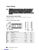
background image


Jumpers and Connectors 

System Board Connectors 

This section provides specific information about the system jumpers. It also 
provides some basic information on jumpers and switches and describes the 
connectors on the various boards in the system. 
 

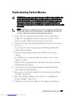
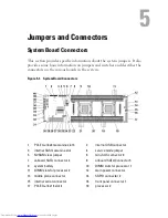
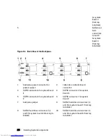
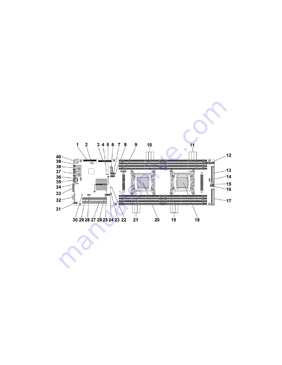
Figure 5-1.   System Board Connectors 


PCI-E Gen3 x8 mezzanine slot 3  

internal USB connector 

internal SAS mezzanine slot  

service mode jumper  

NVRAM clear jumper  

mini-SAS connector 0 

onboard SATA connector 4 

onboard SATA Connector 5 

system battery  

10 

DIMM slots for processor 1 

11  DIMM slots for processor 2 

12 

main power connector  

13  middle plane connector  

14 

SGPIO connector 2 

15  internal serial connector  

16 

front panel connector 1 

17  PCI-E Gen3 x16 slot 4 

18 

processor 2 

Summary of Contents for PowerEdge C6220

Page 1: ...Regulatory Model B08S DellPowerEdgeC6220 Systems Hardware Owner s Manual ...

Page 2: ...ghts reserved Reproduction of these materials in any manner whatsoever without the written permission of Dell Inc is strictly forbidden Trademarks used in this text Dell the DELL logo and PowerEdge are trademarks of Dell Inc Intel and Intel Xeon are registered trademarks of Intel Corporation in the U S and other countries Other trademarks and trade names may be used in this publication to refer to...

Page 3: ...tures and Indicators 24 System Board Assembly Configurations 27 LAN Indicator Codes 29 Power and System Board Indicator Codes 31 Power Supply Indicator Codes 32 1400W 32 1200W 33 BMC Heart Beat LED 34 Post Error Code 35 Collecting System Event Log SEL for Investigation 35 System Event Log 39 Processor Error 39 Memory ECC 40 PCI E Error 41 IOH Core Error 42 SB Error 43 POST Start Event 44 ...

Page 4: ...and SD Card Socket Location 57 2 Using the System Setup Program 58 Start Menu 58 System Setup Options at Boot 58 Boot Manager 59 Console Redirection 61 Enabling and Configuring Console Redirection 62 Main Menu 66 Main Screen 66 Advanced Menu 68 Power Management 69 Chassis Power Management 70 CPU Configuration 71 Prefetch Configuration 75 Memory Configuration 76 SATA Configuration 78 PCI Configurat...

Page 5: ...rfaces for Setup options 98 3 Installing System Components 130 Safety Instructions 130 Recommended Tools 130 Inside the System 131 Hard Drives 133 Removing a 3 5 inch Hard Drive Blank 133 Installing a 3 5 inch Hard Drive Blank 133 Removing a 2 5 inch Hard Drive Blank 134 Installing a 2 5 inch Hard Drive Blank 134 Removing a Hard Drive Carrier 135 Installing a Hard Drive Carrier 136 Removing a Hard...

Page 6: ...affle 145 Heat Sinks 145 Removing the Heat Sink 145 Installing the Heat Sink 146 Processors 147 Removing a Processor 147 Installing a Processor 149 Interposer Extender for 2U Node 151 Removing the Interposer Extender for 2U Node 151 Installing the Interposer Extender for 2U Node 152 Removing the Interposer Extender Tray for 2U Node 153 Installing the Interposer Extender Tray for 2U Node Tray 154 E...

Page 7: ... Node 171 Installing the LSI 9265 8i Card for 2U Node 175 Cable Routing for LSI 9265 8i Card 2U Node 176 LSI 9265 8i RAID Battery 180 Removing the LSI 9265 8i raid battery Assembly 180 Installing the LSI 9265 8i raid Battery Assembly 181 Removing the LSI 9265 8i RAID Battery 182 Installing the LSI 9265 8i RAID Battery 183 Riser card 184 Optional Riser Cards 184 Removing the Riser card for 1U Node ...

Page 8: ...E Mezzanine Card 202 Installing the 10GbE Mezzanine Card 205 Mezzanine Card Bridge Board 206 Removing the Mezzanine Card Bridge Board 206 Installing the Mezzanine Card Bridge Board 207 System Memory 208 Memory Slot Features 208 Supported Memory Module Configuration 208 Removing the Memory Modules 210 Installing the Memory Modules 212 System Battery 214 Replacing the System Battery 214 System Board...

Page 9: ...Direct Hard Drive Backplane 242 Cable Routing for Middle Plane to 2 5 Hard Drive Backplane for Expander Configuration 247 Direct Backplanes 249 Removing the Direct Backplane 249 Installing the Direct Backplane 254 2 5 inch Hard Drive Expander Configuration 256 Removing the 2 5 inch Hard Drive Backplane for Expander Configuration 256 Installing the 2 5 inch Hard Drive Backplane for Expander Configu...

Page 10: ...ration to POST 278 Safety First For You and Your System 278 Installation Problems 279 Troubleshooting System Startup Failure 279 Troubleshooting External Connections 279 Troubleshooting the Video Subsystem 280 Troubleshooting a USB Device 280 Troubleshooting a Serial I O Device 281 Troubleshooting a NIC 281 Troubleshooting a Wet System 282 Troubleshooting a Damaged System 283 Troubleshooting the S...

Page 11: ...lane 298 2 5 Hard Drive Expander Backplane 300 Middle Plane Connectors 301 Interposer Extender for 2U Node Connectors 302 LSI 2008 SAS Mezzanine Card Connectors 303 1GbE Mezzanine Card Connectors 304 10GbE Mezzanine Card Connectors 305 Power Distribution Board 1 Connectors 306 Power Distribution Board 2 Connectors 307 Sensor Board Connectors 307 Jumper Settings 308 System Configuration Jumper Sett...

Page 12: ...to select boot device on page 59 F12 Starts Preboot eXecution Environment PXE iSCSI boot Ctrl C Enters the LSI 2008 SAS Mezzanine Card Configuration Utility For more information see the SAS adapter documentation Ctrl H Enters the LSI 9265 8i Card Configuration Utility For more information see the documentation for your SAS RAID card Ctrl Y Enters the MegaCLI SAS RAID Management Tool Ctrl S Enters ...

Page 13: ...icators Figure 1 1 Front Panel 3 5 x12 Hard Drives With Four System Boards Figure 1 2 Front Panel 3 5 x12 Hard Drives With Two System Boards Figure 1 3 Front Panel 3 5 x6 Hard Drives With One System Board NOTE Figure 1 3 supports at most 6 hard drives ...

Page 14: ...Front Panel 2 5 x8 Hard Drives With One System Board Figure 1 6 Front Panel 2 5 x16 Hard Drives With Two System Boards NOTE Figure 1 2 Figure 1 3 Figure 1 5 and Figure 1 6 only support the 2U node system with the configurations of interposer extender and LSI9265 8i card or LSI 2008 SAS mezzanine card ...

Page 15: ... 2 5 x24 Hard Drives With Two System Boards Figure 1 9 Front Panel 2 5 x24 Hard Drives With Three System Boards Figure 1 10 Front Panel 2 5 x24 Hard Drives With Four System Boards Figure 1 7 Front Panel 2 5 x24 Hard Drives With One System Board ...

Page 16: ...nstalled in the system NOTE On ACPI compliant operating systems turning off the system using the power button causes the system to perform a graceful shutdown before power to the system is turned off NOTE To force an ungraceful shutdown press and hold the power button for 5 seconds 3 Power on indicator system state indicator power button for system board 2 7 Power on indicator system state indicat...

Page 17: ... system status indicator on the front and back blink until the button is pushed again 4 System identification indicator button for system board 2 6 System identification indicator button for system board 4 8 System identification indicator button for system board 3 5 Hard Drives Up to twelve hot swappable 3 5 inch hard drives Up to twenty four hot swappable 2 5 inch hard drives Drive Cover Applica...

Page 18: ...Figure 1 11 3 5 inch Hard Drive Indicators 1 hard drive activity indicator green 2 hard drive status indicator green and amber Figure 1 12 2 5 inch Hard Drive Indicators 1 hard drive status indicator green and amber 2 hard drive activity indicator green ...

Page 19: ...Green Amber Onboard Controller SATA2 Drive on line Off Blinking when active On Off Fail Off On Off LSI 9265 LSI 2008 LSI 9210 SAS SATA2 Slot Empty Off Off Off Drive On line Access Blinking when active On Off Drive Fail Off Off On 150 ms Off 150 ms Drive Rebuild Blinking when active On 400 ms Off 100 ms Off Drive Identify Blinking when active On 250 ms Off 250 ms Off ...

Page 20: ...lot Empty Off Off Off Drive On line Blinking when active On Off Drive Identify Preparing for Removal Blinking when active On 250 ms Off 250 ms Off Drive Rebuild Blinking when active On 400 ms Off 100 ms Off Drive Failed Off Off On 150 ms Off 150 ms Predicted Failure SMART Blinking when active On 500 ms Off 500 ms Off 1000 ms Off 500 ms On 500 ms Off 1000 ms Rebuild Abort Off On 3000 ms Off 9000 ms...

Page 21: ...About Your System 21 Service Tag The Service Tag locations for 1U node 2U node and chassis are as follows Figure 1 13 Service Tag Location for 1U Node Figure 1 14 Service Tag Location for 2U Node ...

Page 22: ...22 About Your System Figure 1 15 Service Tag Location on the Left Front Panel Figure 1 16 Service Tag Location on the Chassis ...

Page 23: ...s for four system boards is presented as below Please refer to Front Panel Features and Indicators on page 13 for other configurations Figure 1 17 Service Tag Linkage NOTE HDD s under warranty would be linked to the appropriate service tag of the node ...

Page 24: ...ck Panel with Four System Boards Figure 1 19 Back Panel with Two System Boards Item Indicator Button Or Connector Icon Description 1 Power supply 2 1200 W 1400 W 2 Power supply 1 1200 W 1400 W 3 USB ports 2 Connect USB devices to the system The ports are USB 2 0 compliant ...

Page 25: ...n cause the indicator to flash blue to identify a particular system and system board Lights amber when the system needs attention due to a problem 5 LAN connector 1 Embedded 10 100 1000 NIC connectors 6 LAN connector 2 Embedded 10 100 1000 NIC connectors 7 Management port Dedicated management port 8 Serial port Connects a serial device to the system 9 VGA port Connects a VGA display to the system ...

Page 26: ... controls the DC power supply output to the system NOTE When powering on the system the video monitor can take from several seconds to over 2 minutes to display an image depending on the amount of memory installed in the system NOTE On ACPI compliant operating systems turning off the system using the power button causes the system to perform a graceful shutdown before power to the system is turned...

Page 27: ...embly Configurations Figure 1 20 Enumeration Four System Boards for 1U Node Figure 1 21 Enumeration Three System Boards for 1U Node Figure 1 22 Enumeration Two System Boards for 1U Node Figure 1 23 Enumeration One System Boards for 1U Node ...

Page 28: ...28 About Your System Figure 1 24 Enumeration Two System Boards for 2U Node Figure 1 25 Enumeration One System Boards for 2U Node ...

Page 29: ...cator Solid amber Linking at 100Mbps speed Solid green Linking at 1Gbps speed maximum Blinking green Linking at 1Gbps speed Activity is present Pre OS POST OS without driver OS with driver Blinking at speed relative to packet density Off Linking at 10Mbps speed Link activity indicator Solid green No access Blinking green LAN accessing Link up Off Idle ...

Page 30: ... speed indicator 2 link activity indicator Component Indicator Condition Speed indicator Blinking green Linking at 100Mbps speed maximum Blinking amber Linking at 10Mbps speed Link activity indicator Solid green No access Blinking green LAN accessing Link up Off Idle ...

Page 31: ... status associated with the status codes Table 1 3 Status Indicator Codes Component Indicator Condition Power on indicator A bi color LED on power button Green Solid Power On S0 Amber Off Green Off BMC critical condition event in Power Off mode S4 S5 Amber Solid Green Off BMC critical condition event in Power On mode S0 Amber Solid System identification indicator Steady Blue IPMI via Chassis Ident...

Page 32: ...wer Supply Indicator Codes 1400W Figure 1 28 Power Supply Status Indicator 1 power supply 2 AC power indicator Component Indicator Condition AC power indicator Solid green System is on Blinking green System is off Off AC off ...

Page 33: ...About Your System 33 1200W Figure 1 29 Power Supply Status Indicator 1 power supply 2 AC power Indicator Component Indicator Condition AC power indicator Solid green AC on Yellow Fault Off AC off ...

Page 34: ...provides BMC heart beat LED LED17 for BMC debugs The BMC heart beat LED is green When the system AC power is connected this LED lights When BMC firmware is ready the BMC heart beat LED blinks Figure 1 30 BMC Heart Beat LED 1 BMC heart beat LED 2 system board ...

Page 35: ... Response section in the following table is divided into 3 types 1 Warning or Not an error The message is displayed on the screen An error record is logged to the SEL The system will continue booting with a degraded state The user may want to replace the erroneous unit 2 Pause The message is displayed on the screen an error is logged to the SEL and user input is required to continue or not dependi...

Page 36: ...device is well 0017h ISA Floppy Input Error Floppy initialization failed Make sure floppy device is well 0018h ISA Floppy Output Error Floppy initialization failed Make sure floppy device is well 0019h USB Read Error USB initialization failed Check USB port is well 001Ah USB Write Error USB initialization failed Check USB port is well 001Bh USB Interface Error USB port initialization failed Check ...

Page 37: ...r PCI device initialization failed Make sure PCI device is well 0028h PCI IO Read Error PCI device initialization failed Make sure PCI device is well 0029h PCI IO Write Error PCI device initialization failed Make sure PCI device is well 002Ah Serial Port not Detected Serial controller initialization failed Make sure serial controller is well 002Bh Serial Port Controller Error Serial controller ini...

Page 38: ...to port 3 8016h SATA 4 Device not Found SATA 4 device not found Install SATA device to port 4 8017h SATA 5 Device not Found SATA 5 device not found Install SATA device to port 5 8018h Sparing Mode is not be Configured Please check Memory Configuration Memory sparing mode failed Change memory configuration for sparing mode 8019h Mirror Mode is not be Configured Please check Memory Configuration Mem...

Page 39: ... this specification 5 Sensor Type 07h Processor 6 Sensor Number 04h Processor Sensor Number depends on platform 7 Event Direction Event Type 6Fh Bit 7 0 Assert Event Bit 6 0 Event Type Code 8 Event Data1 AXh 00h IERR 01h Thermal Trip 02h FRB1 BIST Failure 03h FRB2 Hang in POST Failure 04h FBR3 Processer Startup Initialization Failure 0Ah Processor Automatically Throttled 9 Event Data2 XXh 00h Proc...

Page 40: ...or Type 0Ch Memory 6 Sensor Number 60h Memory Sensor Number depend on platform 7 Event Direction Event Type 6Fh Bit 7 0 Assert Event Bit 6 0 Event Type Code 8 Event Data1 AXh 00h Correctable ECC Error 01h Uncorrectable ECC Error 03h Memory Scrub Failed 04h Memory Device Disabled 08h Spare 9 Event Data2 XXh Bit 7 4 0x00 SBE warning threshold 0x01 SBE critical threshold 0x0F Unspecified Bit 3 0 0x00...

Page 41: ...ator ID 01h Generated by BIOS 4 Event Message Format Version 04h Event Message Format Revision 04h for this specification 5 Sensor Type 13h Critical Interrupt 6 Sensor Number 73h PCI Sensor ID depend on platform 7 Event Direction Event Type 6Fh Bit 7 0 Assert Event Bit 6 0 Event Type Code 8 Event Data1 AXh 04h PCI PERR 05h PCI SERR 07h Bus Correctable Error 08h Bus Uncorrectable Error 0Ah Bus Fata...

Page 42: ...r Type C0h OEM Defined Interrupt 6 Sensor Number XXh 71h QPI Sensor ID depend on platform 72h INT Sensor ID depend on platform 7 Event Direction Event Type 6Fh Bit 7 0 Assert Event Bit 6 0 Event Type Code 8 Event Data1 AXh 07h Core 08h Non Fatal 0Ah Fatal 9 Event Data2 XXh Local Error Bit 10 Event Data3 XXh 00h QPI 0 Error 01h QPI 1 Error 02h QPI 2 Error 03h QPI 3 Error 04h QPI 0 Protocol Error 05...

Page 43: ...ype 13h Critical Interrupt 6 Sensor Number 77h SB Sensor ID depend on platform 7 Event Direction Event Type 6Fh Bit 7 0 Assert Event Bit 6 0 Event Type Code 8 Event Data1 AXh 07h Correctable 08h Uncorrectable 9 Event Data2 XXh Bit 7 5Reserved Local error bit number 4 0 00000b HT Periodic CRC Error 00001b HT Protocol Error 00010b HT Flow Control Buffer Overflow 00011b HT Response Error 00100b HT Pe...

Page 44: ...art depend on platform 7 Event Direction Event Type 6Fh Bit 7 0 Assert Event Bit 6 0 Event Type Code 8 Event Data1 AXh 01h OEM System Boot Event 9 Event Data2 XXh 7 4 BIOS 1st Field Version 0 15 3 0 BIOS 2nd Field Version higher 4bits 0 63 10 Event Data3 XXh 7 6 BIOS 2nd Field Version lower 2bits 0 63 5 0 BIOS 3rd Field Version 0 63 POST End Event Byte Field Value Description 1 NetFunLun 10h 2 Pla...

Page 45: ...t Device 0001b Force PXE Boot 0010b NIC PXE Boot 0011b Hard Disk Boot 0100b RAID HDD Boot 0101b USB Storage Boot 0111b CD DVD ROM Boot 1000b iSCSI Boot 1001b uEFI Shell 1010b ePSA Diagnostic Boot 10 Event Data3 FFh FFh Not Present POST Error Code Event Message System Firmware Progress POST error code UBLBh Byte Field Value Description 1 NetFunLun 10h 2 Platform Event Command 02h 3 Generator ID 01h...

Page 46: ...d Value Description 1 NetFunLun 10h 2 Platform Event Command 02h 3 Generator ID 01h Generated by BIOS 4 Event Message Format Version 04h Event Message Format Revision 04h for this specification 5 Sensor Type 12h System Event 6 Sensor Number 89h BIOS Recovery fail depend on platform 7 Event Direction Event Type 6Fh Bit 7 0 Assert Event Bit 6 0 Event Type Code 8 Event Data1 AXh 01h OEM BIOS recovery...

Page 47: ...sage Format Revision 04h for this specification 5 Sensor Type 12h System Event 6 Sensor Number 8Ah ME fail depend on platform 7 Event Direction Event Type 6Fh Bit 7 0 Assert Event Bit 6 0 Event Type Code 8 Event Data1 AXh 01h OEM ME fail Event 9 Event Data2 XXh 01h ME fail 10 Event Data3 FFh FFh Not Present SEL Generator ID Generator ID BIOS 0x0001 BMC 0x0020 ME 0x002C Windows 2008 0x0137 ...

Page 48: ...ip Processor 07h Sensor specific 6Fh SI 01h SC 40h AM 0002h DM 0000h RM 0002h 0002h 0x03 P2 ThermalTrip Processor 07h Sensor specific 6Fh SI 01h SC 40h AM 0002h DM 0000h RM 0002h 0003h 0x04 CPU ERR2 Processor 07h Sensor specific 6Fh SI 01h SC 40h AM 0001h DM 0000h RM 0001h 0005h 0x05 12V Standby Voltage 02h Threshold 01h SI 7Fh SC 59h AM 7A95h DM 7A95h TM 3F3Fh NOTE The abbreviations used in the f...

Page 49: ... 3F3Fh 0009h 0x08 3 3V Voltage 02h Threshold 01h SI 7Fh SC 59h AM 7A95h DM 7A95h TM 3F3Fh 0008h 0x09 3 3V Standby Voltage 02h Threshold 01h SI 7Fh SC 59h AM 7A95h DM 7A95h TM 3F3Fh 001Ah 0x0A Battery low Battery 29h Sensor specific 6Fh SI 67h SC 40h AM 0001h DM 0000h TM 0001h 000Bh 0x40 MEZZ1 TEMP Temperature 01h Threshold 01h SI 7Fh SC 68h AM 0A95h DM 7A95h TM 3838h 000Ch 0x41 CPU1 Temp Temperatu...

Page 50: ...h 000Fh 0x44 DIMM ZONE 2 Temp Temperature 01h Threshold 01h SI 7Fh SC 68h AM 0A95h DM 7A95h TM 3838h 0012h 0x45 PCH Temp Temperature 01h Threshold 01h SI 7Fh SC 68h AM 0A95h DM 7A95h TM 3838h 0017h 0x60 Memory Memory 0Ch Sensor specific 6Fh SI 01h SC 40h AM 0023h DM 0000h RM 0023h 0013h 0xA0 Watchdog Watchdog 2 23h Sensor specific 6Fh SI 67h SC 40h AM 000Fh DM 0000h RM 000Fh 0016h 0xA2 AC lost Eve...

Page 51: ...tatus Power Supply 08h Sensor specific 74h SI 67h SC 40h AM 000Bh DM 000Bh RM 000Bh Dynamic 0xB7 PSU2 Status Power Supply 08h Sensor specific 74h SI 67h SC 40h AM 000Bh DM 000Bh RM 000Bh Dynamic 0xB8 PSU3 Status Power Supply 08h Sensor specific 74h SI 67h SC 40h AM 000Bh DM 000Bh RM 000Bh Dynamic 0xB9 PSU4 Status Power Supply 08h Sensor specific 74h SI 67h SC 40h AM 000Bh DM 000Bh RM 000Bh Dynamic...

Page 52: ...x6F Variable Dynamic 0xC7 HDD 1 Status Drive Slot Bay 0Dh Sensor specific 0x6F Variable Dynamic 0xC8 HDD 2 Status Drive Slot Bay 0Dh Sensor specific 0x6F Variable Dynamic 0xC9 HDD 3 Status Drive Slot Bay 0Dh Sensor specific 0x6F Variable Dynamic 0xCA HDD 4 Status Drive Slot Bay 0Dh Sensor specific 0x6F Variable Dynamic 0xCB HDD 5 Status Drive Slot Bay 0Dh Sensor specific 0x6F Variable Dynamic 0xCC...

Page 53: ...um allowable dry bulb temperature by 1 C 175 meters above 950 meters 1 F per 319 feet 1 of annual operating hours 5 C to 45 C 5 to 90 RH with 26 C dew point For temperatures between 40 C and 45 C de rate maximum allowable dry bulb temperature by 1 C 125 meters above 950 meters 1 F per 228 feet NOTE When operating in the expanded temperature range ambient temperature warnings may be reported in the...

Page 54: ...e card by each MB Matrix of Fresh Air Support of 1U node with 3 5 HDD configuration 10 30 C 35 C 40 C 45 C 130W 8 core 12 HDD 10 HDD 4 HDD 4 HDD w o PCI E card w o mezzanine card 130W 4 core 8 HDD 4 HDD w o PCI E card w o mezzanine card not support not support 135W 4 HDD w o PCI E card 1 mezzanine card not support not support not support ...

Page 55: ...DD configuration 10 30 C 35 C 40 C 45 C 130W 8 core 24 HDD 24 HDD 8 HDD 4 HDD w o PCI E card w o mezzanine card 130W 4 core 16 HDD 4 HDD w o PCI E card 1 mezzanine card not support not support 135W 8 HDD w o PCI E card 1 mezzanine card not support not support not support ...

Page 56: ...configuration 10 30 C 35 C 40 C 45 C 130W 8 core 12 HDD 12 HDD 8 HDD 8 HDD 1 PCI E card w o mezzanine card 130W 4 core 12 HDD 10 HDD 8 HDD 8 HDD 1 PCI E card w o mezzanine card 135W 12 HDD 8 HDD 1 PCI E card 1 mezzanine card 4 HDD 1 PCI E card w o mezzanine card not support ...

Page 57: ...mezzanine card 130W 4 core 24 HDD 24 HDD 16 HDD 8 HDD 1 PCI E card w o mezzanine card 135W 16 HDD 8 HDD 1 PCI E card 1 mezzanine card 4 HDD 1 PCI E card w o mezzanine card not support Micro SD Card and SD Card Socket Location Micro SD Card Socket Location Located on the 1U riser card see Figure 3 33 SD Card Socket Location Located on the 2U riser card see Figure 3 35 ...

Page 58: ...lowing conditions When changing the system configuration configure items such as Hard drives diskette drives and peripherals Password protection from unauthorized use Power management features When a configuration error is detected by the system and you are prompted to make changes to the Setup utility When redefining the communication ports to prevent any conflicts When changing the password or m...

Page 59: ...About Your System 59 F10 Save Settings and exit in BIOS Setup Boot Manager During BIOS POST press F11 can enter Boot Manager to select boot device ...

Page 60: ...60 About Your System If UEFI OS was installed the UEFI OS partition will be present on the boot option Boot Manager UEFI Mode ...

Page 61: ...enterpiece of the console redirection is the BIOS Console The BIOS Console is a Flash ROM resident utility that redirects input and output over a serial or modem connection The BIOS supports console redirection to a serial port If serial port based headless server support is provided by the system the system must provide support for redirection of all BIOS driven console I O to the serial port The...

Page 62: ...steps 1 Connect the serial cable to the serial port and host system For location of the serial port on the back panel see Figure 1 18 item 8 2 Enter the server BIOS setup screen 3 Enter Set BMC LAN Configuration screen and verify the following settings Remote Access enabled Serial port number COM1 Serial Port Mode 115200 8 n 1 Flow Control None Redirection After BIOS POST Always Terminal Type VT10...

Page 63: ...cess about the LAN connection and BIOS setup settings for Dedicated NIC and Shared NIC To enable SOL feature in the mode of Dedicated NIC please perform the following steps 1 Connect the LAN cable to management port For location of management port on the back panel see Figure 1 18 item 7 2 Enter the server BIOS setup screen 3 Enter Set BMC LAN Configuration screen and verify the following settings...

Page 64: ...erver BIOS setup screen 3 Enter Set BMC LAN Configuration screen and verify the following settings Remote Access enabled Serial port number COM2 Serial Port Mode 115200 8 n 1 Flow Control None Redirection After BIOS POST Always Terminal Type ANSI To do this see Remote Access Configuration on page 94 Note that the last four options need to sync with the host and client 4 Enter LAN Configuration scr...

Page 65: ...t Address Serial Console Redirection Enabled COM1 3F8h 2F8h ttyS0 Serial Port Enabled COM1 2F8h 3F8h ttyS1 BMC Serial Over LAN Enabled COM2 as SOL 3F8h 2F8h ttyS1 Management Port Enabled COM2 as SOL 2F8h 3F8h ttyS0 Scorpion Serial Over LAN Enabled COM2 as SOL 3F8h 2F8h ttyS1 Internal Serial Connector Enabled COM2 as SOL 2F8h 3F8h ttyS0 ...

Page 66: ...ptions for the System Setup program change based on the system configuration NOTE The System Setup program defaults are listed under their respective options in the following sections where applicable Option Description System Date Displays the current date System Time Displays the current time Product Name Displays the product name ...

Page 67: ...Version Displays the current Video BIOS version Fan Control Board FW Displays the current fan control board firmware version Note Fan Control Board FW version will not present if not detected ePPID Displays the eppid of the product NIC1 MAC Address Displays the MAC address of NIC1 NIC2 MAC Address Displays the MAC address of NIC2 BMC NIC MAC Address Displays the MAC address of BMC NIC Processor Ty...

Page 68: ...gs to items on these pages may cause the system to malfunction Unless you have experience adjusting these items we recommend that you leave these settings at the default values If making settings to items on these pages causes your system to malfunction or prevents the system from booting open BIOS and choose Load Optimal Defaults in the Exit menu to boot up normally ...

Page 69: ...r mode CPU Power Capping P state 0 default This option can decide the highest performance P state in OS This setting only can be seen when Power Management be selected to OS Control mode Chassis Power Management This option indicates the different power management options that must be provided to support throttling and capping Energy Efficient Policy Balanced default This field sets the Energy Eff...

Page 70: ...not supported power management control of processor only Chassis Power Management Option Description Power Capping The setting controls PSU power servers loading limited in selected watts Energy Throttling This is the policy to take effect when the server detects a PSU emergency failure ...

Page 71: ...Installing System Components 71 CPU Configuration Scroll to this item and press Enter to view the following screen ...

Page 72: ...Value Limit Disabled default Some OS which is NT4 fails if the value returned in EAX is 3 when CPUID instruction is executed with EAX 0 Disabled this setting disables the 3 or less Enabled this setting limits CPUID function to 3 Virtualization Technology Disabled default Enabled applicable processors Disabled unusable in any OS This feature allows the users to set the VT technology in applicable p...

Page 73: ...he C6 is disabled by default Disabled The C6 is disabled by user in their own liability There will be warning message in both the BIOS Setup help text and the pop up message when the option is changing C7 State Enabled default Enabled The C7 is enabled by default Disabled The C7 is disabled by users in their own liability There will be warning message in both the BIOS Setup help text and the pop u...

Page 74: ...echnology CPU RAPL Big Dial Scorpion Nemo only Off default Sets off to disable CPU RAPL feature Power Limit Watt CPU RAPL Big Dial CPU RAPL Small Dial CPU RAPL Small Dial Scorpion Nemo only 0 default Power Limit Watt CPU RAPL Big Dial CPU RAPL Small Dial Prefetch Configuration Configures Prefetch Invisible if CPU do not support ...

Page 75: ...sor Enabled Enables the processor to fetch the adjacent cache line in the other half of the sector Hardware Prefetcher Enabled default Includes MLC Stremaer Prefetcher Enables Disables the Hardware Prefetcher DCU Streamer Prefetcher Enabled default This field enables disables the DCU Streamer Prefetcher Invisible if CPU do not support DCU IP Prefetcher Enabled default This field enables disables t...

Page 76: ...port memory throttling to optimize power acoustics Memory Operating Mode Optimizer Mode default Memory operating mode is set to support Optimizer Sparing Memory mirroring Advanced ECC Demand Scrubbing Enabled default To disable or enable dram scrubbing is the ability to write corrected data back to the memory once a correctable error is detected on read transaction Patrol Scrubbing Enabled default...

Page 77: ...g at 1 25 volts NOTE BIOS will auto restrict selection if DIMM does not support low voltage NUMA Support Enabled default Disabled for BIOS setup to allow users enable the node interleave option This is for NUMA systems that allow memory interleaving across all processor nodes Enabled for BIOS setup to allow users disable the node interleave option This is for NUMA systems that allows memory interl...

Page 78: ...78 Installing System Components SATA Configuration Scroll to this item and press Enter to view the following screen ...

Page 79: ... code as IDE and uses PCI IRQ referred as Native mode This token applies to the first on board SATA controller AHCI Enables the SATA controller Sets the device class code as SATA and sets up the AHCI BARs and registers This token applies to the first on board SATA controller RAID Enables the SATA controller Sets the device class code as RAID and executes the RAID Option ROM This token applies to t...

Page 80: ...ler to Off Auto Sets the 3rd Serial ATA drive controller to Auto enabled if present POST error if not present SATA Port 3 Auto default Off Sets the 4th Serial ATA drive controller to Off Auto Sets the 4th Serial ATA drive controller to Auto enabled if present POST error if not present SATA Port 4 Auto default Off Sets the 5th Serial ATA drive controller to off Auto Sets the 6th Serial ATA drive co...

Page 81: ...en 3 0 Option Description Embedded Network Devices Configure embedded network devices NIC Enumeration Onboard default Onboard Default Sets PXE boot from on board NIC then Add on NIC adapter Add in Sets PXE boot from Add on NIC adapter then on board NIC Active State Power Management Configuration To control Active State Power Management ASPM PCI Slot Configuration Configures PCI add in card PCIe Ge...

Page 82: ...Enabled default Enabled The embedded video controller is enabled and it is the primary video device Disabled The embedded video controller is disabled Video Enumeration Onboard default Onboard The onboard video controller is used for boot time messages Add in The first add in video controller is used for boot time messages Depending on the BIOS search order and system slot layout WHEA Support Disa...

Page 83: ...edded network interface controller Enabled with PXE Enables the system s primary embedded network interface controller full function including its PXE boot ROM Enabled without PXE Enables the system s primary embedded network interface controller but don t enable the NIC s associated PXE or RPL boot ROM iSCSI Remote Boot Enables NIC1 with iSCSI Remote Boot ...

Page 84: ...k interface controller Enabled with PXE Enables the system s secondary embedded network interface controller full function including its PXE boot ROM Enabled without PXE Enables the system s secondary embedded network interface controller but don t enable the NIC s associated PXE or RPL boot ROM iSCSI Remote Boot Enables NIC2 with iSCSI Remote Boot ...

Page 85: ...Enable DHCP Disabled default Disables Enables DHCP Initiator IP Address Initiator Subnet Mask Gateway Enters IP address in dotted decimal notation Target IP Target IP Address Target Port Boot LUN Targets Name Enters IP address in dotted decimal notation Targets Port Hexadecimal representation of LU number CHAP Type None default None one way CHAP or mutual CHAP ...

Page 86: ...Controls the level of ASPM supported on the given PCI E Link of port 2 L1 entry is enabled Onboard LAN ASPM Disabled default Disabled Controls the level of ASPM supported on the PCI E Link of port4 All entry is disabled L1 Controls the level of ASPM supported on the given PCI E Link of port4 L1 entry is enabled Mezzanine Slot ASPM Disabled Controls the level of ASPM supported on the PCI E Link of ...

Page 87: ...s enabled NB SB Link ASPM L1 default Disabled Controls the level of ASPM supported on the NB SB All entry is disabled L1 Controls the level of ASPM supported on the NB SB L1 entry is enabled PCI Slot Configuration Option Description PCIe Slot Enabled default This feature will allow user to enable disable PCI E Slot and without option ROM initialization ...

Page 88: ...rt with BMC Enabled default This feature allows the users to electrically disable enable the internal USB port which contacts to BMC External USB Port1 Enabled default This feature allows the users to electrically disable enable the external USB port 1 External USB Port2 Enabled default This feature allows the users to electrically disable enable the external USB port 2 Internal USB Connector Enab...

Page 89: ... press Enter to view the following screen Option Description Supervisor Password Displays whether the supervisor password is installed or not User Password Displays whether the user password is installed or not Change Supervisor Password Installs or changes the password Change User Password Installs or changes the password ...

Page 90: ...s to Setup utility User Access Level Limited default Limited Only limited fields can be changed No Access Prevent user access to setup utility View Only Access to setup utility allowed but the fields cannot be changed Full Any field can be changed except the Supervisor password Change User Password Installs or changes the password and the length of password must be greater than one character Clear...

Page 91: ... and press Enter to view the following screen Option Description Status of BMC Displays the BMC status IPMI Specification Version Displays the IPMI specification version BMC Firmware Version Displays the BMC firmware version NIC1 MAC Address Displays the NIC1 MAC address NIC2 MAC Address Displays the NIC2 MAC address ...

Page 92: ...ll stay off Power On After an AC power loss when AC power is restored the system will power on Last State After an AC power loss when AC power is restored the system will return to the state which is when power was lost Power Staggering AC Recovery Immediate default Sets the Power Staggering AC Recovery time to immediate Random User Defined mode Power Button Enabled default Enabled Default Enables...

Page 93: ... Displays the channel number status BMC LAN Port Configuration Shared NIC default Sets BMC LAN Port to dedicated NIC or shared NIC BMC NIC IP Source DHCP default Sets BMC LAN to get LAN IP from Static DHCP mode IP Address Sets BMC LAN IP address Subnet Mask Sets BMC LAN subnet mask Gateway Address Sets BMC LAN Gateway address IPv6 Mode Disabled default Enables or disables IPv6 internet protocol su...

Page 94: ...94 Installing System Components Remote Access Configuration Select Remote Access Configuration to view the following submenu ...

Page 95: ...ode 115200 8 n 1 default Console Redirection baud rate will be set to 115 200 57 600 38 400 19 200 9 600 bits per second Flow Control None default Remote access flowcontrols by none hardware software Redirection After BIOS POST Always default Always The BIOS console redirection if enabled continues to operate after the OS boot hand off Disabled The BIOS console redirection if enabled operates duri...

Page 96: ...the splash or summary screen rather than the detail of the POST flow Disabled Disables the display of the splash or summary screen The user is able to see the detail of the POST messages Pause on Errors Disabled default Enables Disables the BIOS from prompting for F1 F2 on error BIOS pauses at F1 F2 prompt Force PXE Boot Only Disabled default Enables Disables PXE to be the boot device only The sys...

Page 97: ...d Extensible Firmware Interface UEFI BIOS Enables booting to Legacy mode ensures compatibility with operating systems that do not support UEFI Boot Type Order Configures Boot Type Order Network Hard Disk RAID USB Storage CD DVD ROM Exit Menu Scroll to this item and press Enter to view the following screen ...

Page 98: ...tomized default values for all the setup questions Save Customized Defaults Saves all setup questions current values as Customized default Command Line Interfaces for Setup options The options of SETUP menu allow the user to control by system configuration utility syscfg the utility includes in Dell OpenManage Deployment Toolkit DTK Users can use the utility as following To change the SETUP option...

Page 99: ...o hard disk then option ROMs if the devices are available 0053 N A For the next system boot set the IPL priority to Network hard disk RAID USB storage CD DVD ROM if the devices are available 0054 N A For the next system boot set the IPL priority to CD DVD ROM USB Storage hard disk RAID Network if the devices are available 005C N A Enables the BIOS remote update on the next reboot to search for an ...

Page 100: ...A3 Restore on AC Power Loss After an AC power loss when AC power is restored the system will power on 00BA Embedded NIC2 Disable the system s secondary embedded network interface controller 00BB Embedded NIC2 Enable the system s secondary embedded network interface controller but don t enable the NIC s associated PXE or RPL boot ROM 00BC Embedded NIC2 Enable the system s secondary embedded network...

Page 101: ...controller to Auto enabled if present POST error if not present 011B SATA Port2 Sets the 3rd Serial ATA drive controller to OFF 011C SATA Port2 Sets the 3rd Serial ATA drive controller to Auto enabled if present POST error if not present 011D SATA Port3 Sets the 4th Serial ATA drive controller to OFF 011E SATA Port3 Sets the 4th Serial ATA drive controller to Auto enabled if present POST error if ...

Page 102: ...t Capability When disabled Intel processors that support the eXecute Disable XD feature will not report the support to the operating system 0141 Execute Disable XD Bit Capability When enabled Intel processors that support the eXecute Disable XD feature will report the support to the operating system If the operating system supports this extended paging mechanism it will provide some protection aga...

Page 103: ...fetcher Disables the processor s HW prefetcher 0174 Hardware Prefetcher Enables the processor HW prefetcher 0178 Remote Access Enables Serial Console Redirection 0189 External USB PORT2 This feature will allow the users to electrically disable the external USB port2 018A External USB PORT2 This feature will allow the users to electrically enable the external USB port2 0199 Power Saving Features Th...

Page 104: ...m s third embedded network interface controller 01F1 Embedded NIC3 Enables the system s third embedded network interface controller but don t enable the NIC s associated PXE or RPL boot ROM 01F2 Embedded NIC3 Enables the system s third embedded network interface controller full function including its PXE boot ROM 01F3 Embedded NIC3 Enables NIC3 with iSCSI Remote Boot 0204 VT for Direct I O Disable...

Page 105: ... Single core of the processor is enabled This is applicable for Quad core and Dual Core processors 024B C States Sets to enable default the processor can operate in all available Power C States 024C C States Sets to disable there are no C states available for the processor 024D Pause on Errors Enables the BIOS from prompting for F1 F2 on error BIOS pauses at F1 F2 prompt 024E Pause on Errors Disab...

Page 106: ...ield controls the number of enabled 6 cores in each processor By default the maximum number of cores per processor will be enabled 0270 Active Processor Cores This field controls the number of enabled 8 cores in each processor By default the maximum number of cores per processor will be enabled 0271 Active Processor Cores This field controls the number of enabled 10 cores in each processor By defa...

Page 107: ...ware prefetches when detecting strides for prefetch requests default 02AD SR IOV Global Enable Enables BIOS support for SRIOV devices 02AE SR IOV Global Enable Disables BIOS support for SRIOV devices 02B6 Memory Operating Voltage Indicates all DIMMs in the system are operating at 1 5 volts 02B7 Memory Operating Voltage Indicates all DIMMs in the system are operating at 1 35 volts 02B8 Memory Opera...

Page 108: ...operates in ANSI emulation model See also tokens BFh C0h and D7h 401C Redirection After BIOS POST The BIOS console redirection if enabled continues to operate after the OS boot hand off 401D Redirection After BIOS POST The BIOS console redirection if enabled operates during the BIOS boot only and is disabled prior to OS boot hand off See also tokens BFh C0h D7h 401Ah and 401Bh 4022 1st Boot Device...

Page 109: ...Console Redirection baud rate will be set to 19 200 bits per second 4036 Serial Port Mode Console Redirection baud rate will be set to 9 600 bits per second 403F Clear SMBIOS System Event Log The system event log to be cleared on the next boot 4800 Node Manager Allows user to enable the Node Manager mode for Intel CPUs 4801 APML Allows user to enable the Advanced Platform Management Link mode for ...

Page 110: ...arning message in both the BIOS Setup help text and the pop up message when the option is changing 480F C7 State The C7 is enabled by default 4810 Non Coherent HT Link Width Set HT Link to 8 bit width 4811 Non Coherent HT Link Width Set HT Link 16 to bit width 4812 Non Coherent HT Link Speed Set HT Link speed as 800MHz 4813 Non Coherent HT Link Speed Set HT Link speed as 1000MHz 4814 Non Coherent ...

Page 111: ...ata back to the memory once a correctable error is detected on a read transaction 482B DRAM Scrubbing Enables Dram scrubbing is the ability to write corrected data back to the memory once a correctable error is detected on a read transaction 482C Demand Scrubbing Disables Demand scrubbing is the ability to write corrected data back to the memory once a correctable error is detected on a read trans...

Page 112: ...l of ASPM supported on the given PCI E Link of port L0s entry enabled 4842 PCI E Slot ASPM Controls the level of ASPM supported on the given PCI E Link of port L1 entry enabled 4843 PCI E Slot ASPM Controls the level of ASPM supported on the given PCI E Link of port L0s and L1 entry enabled 4844 PCI E Slot ASPM Controls the level of ASPM supported on the given PCI E Link of port L0s entry downstre...

Page 113: ...ported on Mezzanine Slot L1 entry enabled 484F Mezzanine Slot ASPM Controls the level of ASPM supported on Mezzanine Slot L0s and L1 entry enabled 4850 Mezzanine Slot ASPM Controls the level of ASPM supported on Mezzanine Slot L0s entry downstream enabled 4851 Mezzanine Slot ASPM Controls the level of ASPM supported on Mezzanine Slot L0s entry downstream and L1 enabled 4852 NB SB Link ASPM Control...

Page 114: ... feature which repurposes the traditional Wake on LAN WOL signal to reboot the motherboard During system is in S0 S3 state when a WOL packet is received by the NIC the wake up signal generated by the NIC shall cause a hardware reboot of the motherboard 485F Reboot on WOL ROW Enables the ROW Reboot on WOL ROW is a feature which repurposes the traditional Wake on LAN WOL signal to reboot the motherb...

Page 115: ...3 487F Mezzanine Slot This feature will allow the users to electrically disable Mezzanine Slot 4880 Mezzanine Slot This feature will allow the users to electrically enable Mezzanine Slot 4881 1st Boot Device Sets Hard Disk as first boot device 4882 1st Boot Device Sets RAID as first boot device 4883 1st Boot Device Sets USB Storage as first boot device 4884 1st Boot Device Sets CD DVD ROM as first...

Page 116: ...SPMI Table Disables the ACPI SPMI Table for BMC ROM update 48A1 ACPI SPMI Table Enables the ACPI SPMI Table for IPMI driver installation 48A2 BMC LAN Port Configuration Sets BMC LAN Port to Dedicated NIC 48A3 BMC LAN Port Configuration Sets BMC LAN Port to Shared NIC 48A4 BMC NIC IP Source Sets BMC LAN to get LAN IP from Static mode 48A5 BMC NIC IP Source Sets BMC LAN to get LAN IP from DHCP mode ...

Page 117: ... E HT etc 48B3 NMI on Error Disables BIOS to generate NMI when PCI E uncorrectable errors occur 48B4 NMI on Error Enables BIOS to generate NMI when PCI E uncorrectable errors occur 48B5 Memory Operating Voltage Indicates all DIMMs in the system are operating at 1 25 volts 48C0 Frequency Ratio Sets frequency multiplier as maximum level 48C1 Frequency Ratio Downgrades frequency multiplier one level ...

Page 118: ...48D8 Load Customized Defaults Requests a customized default of SETUP values on the next boot 48DA Save Customized Defaults Saves current settings to customized defaults of SETUP on next boot 48DB N A Requests maximum performance settings of SETUP values on the next boot 48DC N A Requests a energy efficiency settings of SETUP values on the next boot 48DD N A Requests HPCC efficiency settings of SET...

Page 119: ...e next boot 48E8 N A The HDD3 is used for 1st device of PXE boot on the next boot 48E9 N A The HDD4 is used for 1st device of PXE boot on the next boot 48EA N A The HDD5 is used for 1st device of PXE boot on the next boot 48EB N A The HDD6 is used for 1st device of PXE boot on the next boot 48EC N A The RAID HDD1 is used for 1st device of PXE boot on the next boot 48ED N A The RAID HDD2 is used fo...

Page 120: ...The RAID HDD13 is used for 1st device of PXE boot on the next boot 48F9 N A The RAID HDD14 is used for 1st device of PXE boot on the next boot 48FA N A The RAID HDD15 is used for 1st device of PXE boot on the next boot 48FB N A The RAID HDD16 is used for 1st device of PXE boot on the next boot 48FC N A The HDD7 is used for 1st device of HDD boot on the next boot 48FD N A The HDD8 is used for 1st d...

Page 121: ...g event trigger 4913 Sled Level Policy Set sled level policy as throttling when Emergency Throttling event trigger 4914 Sled Level Policy Set sled level policy as throttling when Emergency Throttling event trigger 4915 Sled Level Policy Set sled level policy as throttling when Emergency Throttling event trigger 4916 Chassis Level Policy Default set chassis level policy as throttling when Emergency...

Page 122: ...122 Installing System Components Token Setup option Description 4875 Perfmon and DFX Devices Disable Perfmon and DFX Devices 4876 Perfmon and DFX Devices Enable Perfmon and DFX Devices ...

Page 123: ...et Configurable Commands App 0x06 0x0C O Y Get Configurable Command Sub functions App 0x06 0x0D O Y Set Command Enables App 0x06 0x60 O Y Get Command Enables App 0x06 0x61 O Y Set Command Sub function Enables App 0x06 0x62 O Y Get Command Sub function Enables App 0x06 0x63 O Y Get OEM NetFn IANA Support App 0x06 0x64 O Y BMC Watchdog Timer Commands Reset Watchdog Timer App 0x06 0x22 M Y Set Watchd...

Page 124: ...pp 0x06 0x40 O Y Get Channel Access App 0x06 0x41 O Y Get Channel Info App 0x06 0x42 O Y Set User Access App 0x06 0x43 O Y Get User Access App 0x06 0x44 O Y Set User Name App 0x06 0x45 O Y Get User Name App 0x06 0x46 O Y Set User Password App 0x06 0x47 O Y Activate Payload App 0x06 0x48 O Y Deactivate Payload App 0x06 0x49 O Y Get Payload Activation Status App 0x06 0x4A O Y Get Payload Instance In...

Page 125: ... O Set System Boot Options Chassis 0x00 0x08 O Get System Boot Options Chassis 0x00 0x09 O Get POH Counter Chassis 0x00 0x0F O Event Commands Set Event Receiver S E 0x04 0x00 M Y Get Event Receiver S E 0x04 0x01 M Y Platform Event or Event Message S E 0x04 0x02 M Y PEF and Alerting Commands Get PEF Capabilities S E 0x04 0x10 M Y Arm PEF Postpone Timer S E 0x04 0x11 M Y Set PEF Configuration Parame...

Page 126: ...t FRU Inventory Area Info Storage 0x0A 0x10 M Y Read FRU Data Storage 0x0A 0x11 M Y Write FRU Data Storage 0x0A 0x12 M Y SDR Device Commands Get SDR Repository Info Storage 0x0A 0x20 M Y Get SDR Repository Allocation Info Storage 0x0A 0x21 O Reserve SDR Repository Storage 0x0A 0x22 M Y Get SDR Storage 0x0A 0x23 M Y Add SDR Storage 0x0A 0x24 M Partial Add SDR Storage 0x0A 0x25 M Y Delete SDR Storag...

Page 127: ...0x0C 0x02 M Y Suspend BMC ARPs Transport 0x0C 0x03 O Get IP UDP RMCP Statistics Transport 0x0C 0x04 O Serial Modem Device Commands Set Serial Modem Configuration Transport 0x0C 0x10 M Y Get Serial Modem Configuration Transport 0x0C 0x11 M Y Set Serial Modem Mux Transport 0x0C 0x12 O Y Get TAP Response Codes Transport 0x0C 0x13 O Set PPP UDP Proxy Transmit Data Transport 0x0C 0x14 O Get PPP UDP Pro...

Page 128: ... Firmware 0x08 0x16 O Y Table 2 3 The Power Management Settings Setup Menu Setting Maximum Performance 48DB Energy Efficiency 48DC Setup Page Setting Option D4 Token Option D4 Token Power Management Power Management Max Performance 021F Node Manager 4800 Energy Efficiency Policy Performance 48D0 Low Power 48D2 Processor Configuration Active Processor Cores All 026E 1 2 0233 0232 Frequency Ratio Au...

Page 129: ...02B6 1 35V 1 25V 02B7 48B5 SATA Configuration Embedded SATA Link State Auto 4834 1 5 Gbps 4835 Power Saving Features Disabled 0199 Enabled 019A PCI Configuration PCI E Slot ASPM Disabled 4840 L0s L1 4843 Onboard LAN ASPM Disabled 4846 L0s L1 4849 Mezzing Slot ASPM Disabled 484C L0s L1 484F NB SB Link ASPM Disabled 4852 L1 4853 PCI E Generation Gen3 Gen2 485B 4 85C Gen1 485D NOTE The PCI E Gen2 x16...

Page 130: ... your warranty Read and follow the safety instructions that came with the product To avoid injury to yourself or damage to system follow these guidelines Always disconnect the system from the power outlet whenever you are working inside the system If possible wear a grounded wrist strap as you work inside the system Or discharge any static electricity by touching the bare metal chassis of system c...

Page 131: ...icing that is not authorized by Dell is not covered by your warranty Read and follow the safety instructions that came with the product CAUTION This system must be operated with the system cover installed to ensure proper cooling NOTE The illustration in this section shows a system with 12 x3 5 inch hard drives as an example Figure 3 1 Inside the System with 1U Node 1 system board assembly 4 2 pow...

Page 132: ...132 Installing System Components 1 system board assembly 2 2 power supply 2 3 power distribution board 2 4 cooling fan 4 5 hard drive bay 6 hard drive 12 ...

Page 133: ...NOTE This section is applicable to systems with hot swappable hard drives only 1 Pull the hard drive blank out of the hard drive bay See Figure 3 3 Figure 3 3 Removing or Installing a 3 5 inch Hard Drive Blank 1 3 5 inch hard drive blank Installing a 3 5 inch Hard Drive Blank 1 Slide the hard drive blank into the drive bay until the hard drive blank is seated in place See Figure 3 3 ...

Page 134: ... the handle to remove the 2 5 inch hard drive blank out of the hard drive bay See Figure 3 4 Figure 3 4 Removing or Installing a 2 5 inch Hard Drive Blank 1 2 5 inch hard drive blank 2 handle 3 latch Installing a 2 5 inch Hard Drive Blank 1 With the latch side facing up slide the latch into the hard drive bay first 2 Push the 2 5 inch hard drive with a slight inclination into the hard drive bay un...

Page 135: ...e online or telephone service and support team Damage due to servicing that is not authorized by Dell is not covered by your warranty Read and follow the safety instructions that came with the product CAUTION To maintain proper system cooling all empty hard drive bays must have drive blanks installed 1 Turn the lock lever counterclockwise until it points to the unlock symbol 2 Slide the release bu...

Page 136: ...the release handle to lock the hard drive in place 3 Turn the lock lever clockwise to the lock symbol See Figure 3 5 Removing a Hard Drive from a Hard Drive Carrier CAUTION Many repairs may only be done by a certified service technician You should only perform troubleshooting and simple repairs as authorized in your product documentation or as directed by the online or telephone service and suppor...

Page 137: ...e the partially installed carrier s shield spring and make it unusable CAUTION To prevent data loss ensure that your operating system supports hot swappable drive installation See the documentation supplied with the operating system 1 Remove the four screws See Figure 3 6 2 Lift the hard drive out of the hard drive carrier Figure 3 6 Removing and Installing a Hard Drive from the Hard Drive Carrier...

Page 138: ...here power supply redundancy is guaranteed NOTE Configurations higher than indicated in the table may change the power supply mode to non redundant In non redundant mode if the power requirement exceeds the installed system power capacity the BIOS will throttle the processors Also if Processor Power Capping is enabled then processor throttling occurs on configurations that exceed the cap value NOT...

Page 139: ...and follow the safety instructions that came with the product CAUTION The System requires at least one power supply to operate normally 1 It is recommended to turn off the system including any attached peripherals and disconnect the system from the electrical outlet 2 Disconnect the power cable from the power source and the power supply 3 Press the release lever and using the handle slide the powe...

Page 140: ...th the product CAUTION The System requires at least one power supply to operate normally 1 Verify that both power supplies are of the same type and have the same maximum output power NOTE The maximum output power is printed on the power supply label 2 Slide the new power supply into the chassis until the power supply is fully seated and the release lever snaps into place See Figure 3 7 3 Connect t...

Page 141: ... the online or telephone service and support team Damage due to servicing that is not authorized by Dell is not covered by your warranty Read and follow the safety instructions that came with the product 1 Remove the screw that secures the retaining latch See Figure 3 8 2 Press the retaining latch and slide the system board blank tray out of the chassis See Figure 3 8 Figure 3 8 Removing and Insta...

Page 142: ...d Assembly CAUTION Many repairs may only be done by a certified service technician You should only perform troubleshooting and simple repairs as authorized in your product documentation or as directed by the online or telephone service and support team Damage due to servicing that is not authorized by Dell is not covered by your warranty Read and follow the safety instructions that came with the p...

Page 143: ...e and support team Damage due to servicing that is not authorized by Dell is not covered by your warranty Read and follow the safety instructions that came with the product 1 Slide the system board assembly into the chassis until it snaps into place See Figure 3 9 2 Reconnect all the external cables to the system board 3 Replace the screw that secures the retaining latch See Figure 3 9 4 Turn on t...

Page 144: ...to servicing that is not authorized by Dell is not covered by your warranty Read and follow the safety instructions that came with the product 1 Remove the system board assembly See Removing a System Board Assembly on page 142 2 When removing the air baffle for 2U node the expansion card assembly for 2U node must be removed first See Figure 3 17 3 Lift the two air baffles out of the system board a...

Page 145: ...Heat Sinks Removing the Heat Sink CAUTION Many repairs may only be done by a certified service technician You should only perform troubleshooting and simple repairs as authorized in your product documentation or as directed by the online or telephone service and support team Damage due to servicing that is not authorized by Dell is not covered by your warranty Read and follow the safety instructio...

Page 146: ...3 11 Removing and Installing the Heat Sink 1 screw 4 2 heat sink Installing the Heat Sink CAUTION Many repairs may only be done by a certified service technician You should only perform troubleshooting and simple repairs as authorized in your product documentation or as directed by the online or telephone service and support team Damage due to servicing that is not authorized by Dell is not covere...

Page 147: ...W 3 5GHz and 12 cores based on Intel Patsburg PCH chipset Removing a Processor CAUTION Many repairs may only be done by a certified service technician You should only perform troubleshooting and simple repairs as authorized in your product documentation or as directed by the online or telephone service and support team Damage due to servicing that is not authorized by Dell is not covered by your w...

Page 148: ... out of the socket and leave the socket release lever up so that the socket is ready for the new processor See Figure 3 12 CAUTION Be careful not to bend any of the pins on the C socket when removing the processor Bending the pins can permanently damage the system board Be sure to properly align the process or notch to the socket and insert straight down Do not move from side to side Figure 3 12 R...

Page 149: ...le download to install the update on your system 1 Unpack the processor if it has not been used previously If the processor has already been used remove any thermal grease from the top of the processor using a lint free cloth 2 Align the processor with the socket keys on the CPU socket See Figure 3 12 CAUTION Positioning the processor incorrectly can permanently damage the system board or the proc...

Page 150: ...Phillips screwdriver tighten the heat sink retention screws See Figure 3 11 10 Replace the system board assembly See Installing a System Board Assembly on page 143 11 Reconnect the system to its electrical outlet and turn on the system including any attached peripherals 12 Press F2 to enter the System Setup program and check that the processor information matches the new system configuration See S...

Page 151: ... online or telephone service and support team Damage due to servicing that is not authorized by Dell is not covered by your warranty Read and follow the safety instructions that came with the product NOTE This section is applicable to systems with 2U node only Removing the Interposer Extender for 2U Node 1 Remove the system board assembly See Removing a System Board Assembly on page 142 2 Disconne...

Page 152: ...certified service technician You should only perform troubleshooting and simple repairs as authorized in your product documentation or as directed by the online or telephone service and support team Damage due to servicing that is not authorized by Dell is not covered by your warranty Read and follow the safety instructions that came with the product 1 Place the interposer extender into the interp...

Page 153: ... is not covered by your warranty Read and follow the safety instructions that came with the product NOTE This section is applicable to systems with 2U node only 1 Remove the system board assembly See Removing a System Board Assembly on page 142 2 Remove the interposer extender See Figure 3 13 3 Remove the screws that secure the interposer extender tray to the system board See Figure 3 14 4 Lift th...

Page 154: ...ender tray to the system board See Figure 3 14 3 Replace the interposer extender See Figure 3 13 4 Connect all the cables to the interposer extender See Figure 5 10 5 Replace the system board assembly See Installing a System Board Assembly on page 143 Expansion Card Assembly and Expansion Card Removing the Expansion Card for 1U Node CAUTION Many repairs may only be done by a certified service tech...

Page 155: ...that secure the expansion card assembly See Figure 3 15 3 Lift the expansion card assembly out of the system board assembly See Figure 3 15 Figure 3 15 Removing the Expansion Card Assembly for 1U Node 1 expansion card assembly 2 screw 4 3 system board assembly ...

Page 156: ... over the empty expansion slot opening and close the expansion card latch See Figure 3 16 NOTE You must install a filler bracket over an empty expansion slot to maintain Federal Communications Commission FCC certification of the system The brackets also keep dust and dirt out of the system and aid in proper cooling and airflow inside the system Figure 3 16 Removing the Expansion Card for 1U Node 1...

Page 157: ...n page 142 3 Remove the four screws that secure the expansion card assembly 4 Lift the expansion card assembly away from the system board assembly 5 Remove the screw securing the filler bracket 6 Grasp the filler bracket by its edges and carefully remove it from the riser card NOTE Keep this bracket in case you need to remove the expansion card Filler brackets must be installed over empty expansio...

Page 158: ...t is not authorized by Dell is not covered by your warranty Read and follow the safety instructions that came with the product 1 Remove the system board assembly See Removing a System Board Assembly on page 142 2 Remove the five screws that secure the expansion card assembly See Figure 3 17 3 Lift the expansion card assembly out of the system board assembly See Figure 3 17 Figure 3 17 Removing the...

Page 159: ...ponents 159 Figure 3 18 5 Remove the expansion card lock cover See Figure 3 18 Figure 3 18 Removing the Expansion card Lock Cover for 2U Node 1 expansion card assembly 2 screw 4 3 expansion card lock cover 4 expansion card ...

Page 160: ...l filler bracket over the empty expansion slot opening and close the expansion card latch See Figure 3 19 NOTE You must install a filler bracket over an empty expansion slot to maintain Federal Communications Commission FCC certification of the system The brackets also keep dust and dirt out of the system and aid in proper cooling and airflow inside the system Figure 3 19 Removing the Expansion Ca...

Page 161: ...161 8 Install the expansion card slot cover and screw securing the expansion card bracket See Figure 3 20 Figure 3 20 Installing the Expansion card Slot Cover for 2U Node 1 screw 2 expansion card slot cover 3 expansion card bracket ...

Page 162: ...y the online or telephone service and support team Damage due to servicing that is not authorized by Dell is not covered by your warranty Read and follow the safety instructions that came with the product CAUTION Expansion cards can only be installed in the slots on the expansion card riser Do not attempt to install expansion cards directly into the riser connector on the system board 1 Unpack the...

Page 163: ...ots to maintain FCC certification of the system The brackets also keep dust and dirt out of the system and aid in proper cooling and airflow inside the system 8 Holding the expansion card by its edges position the card so that the card edge connector aligns with the riser card 9 Insert the card edge connector firmly into the riser card until the card is fully seated 10 Install the expansion slot l...

Page 164: ... SAS SGPIO cable RAID battery cable Cable required for 2U Node Mini SAS SGPIO cable Mini SAS cable RAID battery cable Power cable LSI 9210 8i HBA Same as LSI 9265 8i see LSI 9265 8i Card No RAID Battery Cable required for 1U Node Mini SAS cable Mini SAS SGPIO cable Cable required for 2U node Mini SAS cable Mini SAS SGPIO cable Power cable LSI 9285 8e with RAID Battery Same as Expansion Card see Fi...

Page 165: ...rd for 1U Node CAUTION Many repairs may only be done by a certified service technician You should only perform troubleshooting and simple repairs as authorized in your product documentation or as directed by the online or telephone service and support team Damage due to servicing that is not authorized by Dell is not covered by your warranty Read and follow the safety instructions that came with t...

Page 166: ...cure the LSI 9265 8i card assembly See Figure 3 22 4 Lift the LSI 9265 8i card assembly out of the system board assembly See Figure 3 22 Figure 3 22 Removing the LSI 9265 8i Card Assembly for 1U Node 1 LSI 9265 8i card assembly 2 screw 4 3 system board assembly ...

Page 167: ...ion card slot cover over the empty expansion slot opening and close the expansion card latch NOTE You must install a filler bracket over an empty expansion slot to maintain Federal Communications Commission FCC certification of the system The brackets also keep dust and dirt out of the system and aid in proper cooling and airflow inside the system Figure 3 23 Removing the LSI 9265 8i Card 1 expans...

Page 168: ...mentation accompanying the card 2 Remove the system board assembly See Removing a System Board Assembly on page 142 3 Connect the RAID battery cable to the BBU interposer card See Figure 3 24 4 Remove the screw securing the filler bracket Grasp the filler bracket by its edges and carefully remove it from the riser card NOTE Keep this bracket in case you need to remove the expansion card Filler bra...

Page 169: ...2 Connect the mini SAS SGPIO cable to the LSI 9265 8i card and connect the other end of the cable to the corresponding connectors on the system board Ensure the cables should go through the cable clip ring See Figure 3 24 3 Connect the RAID battery cable to the BBU interposer card on the LSI 9265 8i card and connect the other end of the cable to the corresponding connector on the RAID battery NOTE...

Page 170: ... Item Cable From LSI 9265 8i Card To RAID Battery and System Board Mini SAS cable Mini SAS connector 0 3 J2B1 Mini SAS connector 0 Mini SAS SGPIO cable Mini SAS connector 4 7 J2B2 Onboard SATAII connectors 4 5 and SGPIO 2 RAID battery cable RAID battery connector J4 RAID battery connector ...

Page 171: ...n You should only perform troubleshooting and simple repairs as authorized in your product documentation or as directed by the online or telephone service and support team Damage due to servicing that is not authorized by Dell is not covered by your warranty Read and follow the safety instructions that came with the product NOTE The LSI 9265 8i card can be supported only on the 1 5U riser card For...

Page 172: ... secure the LSI 9265 8i card assembly See Figure 3 25 4 Lift the LSI 9265 8i card assembly out of the system board assembly See Figure 3 25 Figure 3 25 Removing the LSI 9265 8i Card Assembly for 2U Node 1 LSI 9265 8i card assembly 2 screw 5 3 system board assembly ...

Page 173: ... four screws securing the LSI 9265 8i card lock cover See Figure 3 26 6 Remove the LSI 9265 8i card lock cover See Figure 3 26 Figure 3 26 Removing the LSI 9265 8i Card Lock Cover 1 LSI 9265 8i card assembly 2 screws 4 3 expansion card lock cover ...

Page 174: ... a metal filler bracket over the empty expansion slot opening and close the expansion card latch NOTE You must install a filler bracket over an empty expansion slot to maintain Federal Communications Commission FCC certification of the system The brackets also keep dust and dirt out of the system and aid in proper cooling and airflow inside the system Figure 3 27 Removing the LSI 9265 8i Card 1 LS...

Page 175: ...ng a System Board Assembly on page 142 3 Connect the RAID battery cable to the BBU interposer card See Figure 3 28 4 Remove the screw securing the filler bracket Grasp the filler bracket by its edges and carefully remove it from the riser card NOTE Keep this bracket in case you need to remove the expansion card Filler brackets must be installed over empty expansion cards slots to maintain FCC cert...

Page 176: ...gure 3 28 2 Connect the mini SAS cable to the LSI 9265 8i card and connect the other end of the cable to the corresponding connector on the system board Ensure the cables should go through the cable clip ring See Figure 3 28 3 Connect the RAID battery cable to the BBU interposer card on the LSI 9265 8i card and connect the other end of the cable to the corresponding connector on the RAID battery S...

Page 177: ...m LSI 9265 8i Card To RAID Battery and Hard Drive to Backplane SATAII Connectors Mini SAS SGPIO cable Mini SAS connector 0 3 J2B1 SATAII connectors 0 3 and SGPIO 1 on the interposer extender for 2U node Mini SAS cable Mini SAS connector 4 7 J2B2 Mini SAS connector 0 on the system board RAID battery cable RAID battery connector J4 RAID battery connector on the RAID battery power cable Control conne...

Page 178: ...178 Installing System Components 5 Press down on the cables and ensure the cables are routed lower than the height of the expansion card assembly for the 2U node Figure 3 29 Cable Routing Down 2U Node ...

Page 179: ...able tie make the cable tie go through the second air hole from the bottom to the top and then tighten it to encircle one of the mini SAS cables And meanwhile ensure the other mini SAS cable is held by the cable tie clip Figure 3 30 Cable Tie for 2U Node ...

Page 180: ...e information in this section applies only to systems intalled with the LSI 9265 8i card 1 Remove the system board assembly See Removing a System Board Assembly on page 142 2 When removing the LSI 9265 8i RAID battery assembly for 1U node skip to step 5 for 2U node continue the steps 3 Remove the interposer extender See Removing the Interposer Extender on page 151 4 Remove the interposer extender ...

Page 181: ...e screws securing the LSI9265 8i RAID battery assembly See Figure 3 31 3 Connect the cable connecting to the LSI 9265 8i card 4 When replacing the LSI9265 8i RAID battery assembly for 1U node skip to step 7 for 2U node continue the steps 5 Replace the interposer extender tray See Removing the Interposer Extender Tray on page 153 6 Replace the interposer extender for 2U node See Removing the Interp...

Page 182: ...me with the product NOTE The information in this section applies only to systems with the optional RAID controller card 1 Remove the system board assembly See Removing a System Board Assembly on page 142 2 Disconnect the cable connecting to the LSI 9265 8i card 3 When removing the LSI 9265 8i RAID battery for 1U node skip to step 6 for 2U node continue the steps 4 Remove the interposer extender Se...

Page 183: ...ing the LSI 9265 8i RAID Battery 1 Place the LSI 9265 8i RAID battery in position on the LSI 9265 8i RAID battery carrier See Figure 3 32 2 Replace the screws securing the LSI 9265 8i RAID battery to the LSI 9265 8i RAID battery carrier See Figure 3 32 3 Install the LSI 9265 8i RAID battery into the LSI 9265 8i RAID battery carrier See Installing the LSI 9265 8i raid Battery on page 181 4 Reconnec...

Page 184: ...the Interposer Extender on page 151 8 Install the system board assembly See Installing a System Board Assembly on page 143 Riser card Optional Riser Cards Figure 3 33 1U Riser card for 1U Node 1 USB connector 2 PCI E Gen 3 x16 3 micro SD card socket Figure 3 34 1 5U Riser card for 2U Node 1 PCI E Gen 3 x16 ...

Page 185: ...Installing System Components 185 1 PCI E Gen 3 x16 2 USB connector 3 SD card socket Figure 3 35 2U Riser card for 2U Node ...

Page 186: ...thorized by Dell is not covered by your warranty Read and follow the safety instructions that came with the product 1 Remove the system board assembly See Removing a System Board Assembly on page 142 2 Remove the expansion card See Removing the Expansion Card for 1U Node on page 154 3 Remove the two screws securing the riser card to the expansion card bracket See Figure 3 36 4 Pull the riser card ...

Page 187: ...lace the riser card into the expansion card bracket See Figure 3 36 2 Replace the two screws securing the riser card to the expansion card bracket See Figure 3 36 3 Install the expansion card See Installing the Expansion Card for 1U Node on page 157 4 Replace the system board assembly See Installing a System Board Assembly on page 143 Cable Routing for Riser Card 1U Node 1 Connect the USB cable to...

Page 188: ...d by the online or telephone service and support team Damage due to servicing that is not authorized by Dell is not covered by your warranty Read and follow the safety instructions that came with the product NOTE Both 1 5U riser card and 2U riser card can be supported in the 2U node system 1 Remove the system board assembly See Removing a System Board Assembly on page 142 2 Remove the expansion ca...

Page 189: ...e 3 39 4 Remove the two screws securing the 1 5U riser card to the expansion card bracket See Figure 3 38 5 Pull the 1 5U riser card away from the expansion card bracket See Figure 3 38 Figure 3 38 Removing and Installing the 1 5U Riser card 1 screw 2 2 expansion card bracket 3 card holder 4 1 5U riser card ...

Page 190: ...ws securing the 2U riser card to the expansion card bracket See Figure 3 39 7 Pull the 2U riser card away from the expansion card racket See Figure 3 39 Figure 3 39 Removing and Installing the 2U Riser card 1 screw 4 2 expansion card bracket 3 2U riser card ...

Page 191: ...ranty Read and follow the safety instructions that came with the product 2 Place the 2U riser card into the expansion card bracket See Figure 3 39 3 Replace the four screws securing the 2U riser card to the expansion card bracket See Figure 3 39 4 Place the 1 5U riser card into the expansion card bracket See Figure 3 38 5 Replace the two screws securing the 1 5U riser card to the expansion card br...

Page 192: ... USB cable to the 1U riser card and connect the other end of the cable to the corresponding connectors on the system board See Figure 3 40 Figure 3 40 Cable Routing for 2U Riser Card USB Cable 8 Item Cable From Riser Card To System Board USB cable USB connector internal USB connector ...

Page 193: ...ooting and simple repairs as authorized in your product documentation or as directed by the online or telephone service and support team Damage due to servicing that is not authorized by Dell is not covered by your warranty Read and follow the safety instructions that came with the product 1 Remove the system board assembly See Removing a System Board Assembly on page 142 2 Disconnect all the cabl...

Page 194: ... product documentation or as directed by the online or telephone service and support team Damage due to servicing that is not authorized by Dell is not covered by your warranty Read and follow the safety instructions that came with the product 1 Place the LSI 2008 SAS mezzanine card on the system board assembly See Figure 3 41 and Figure 5 11 2 Replace the three screws that secure the LSI 2008 SAS...

Page 195: ...gure 3 42 2 Connect the mini SAS cable to the LSI 2008 SAS Mezzanine card and connect the other end of the cable to the corresponding connector on the system board See Figure 3 42 Figure 3 42 Cable Routing for LSI 2008 SAS Mezzanine Card 1U Node Item Cable From LSI 2008 SAS Mezzanine Card To System Board Mini SAS SGPIO cable Mini SAS connector 4 7 J4 Onboard SATAII connectors 4 5 and SGPIO 2 Mini ...

Page 196: ...power cable to the interposer extender for 2U node and connect the other end of the cable to the corresponding connector on the system board See Figure 3 43 Figure 3 43 Cable Routing for LSI 2008 SAS Mezzanine Card 2U Node Item Cable From LSI 2008 SAS Mezzanine Card To System Board and Hard Drive to Backplane SATAII Connectors Mini SAS cable Mini SAS connector 4 7 J4 Mini SAS connector 0 on the sy...

Page 197: ...em Components 197 4 Press down on the cables and ensure the cables are routed lower than the height of the expansion card assembly for the 2U node Figure 3 44 Cable Routing Down for LSI 2008 SAS Mezzanine Card 2U Node ...

Page 198: ...g the cable tie make the cable tie go through the second air hole from the bottom to the top and then tighten it to encircle one of the mini SAS cables Ensure the other mini SAS cable is held by the cable tie clip Figure 3 45 Cable Tie for 2U Node ...

Page 199: ...e service and support team Damage due to servicing that is not authorized by Dell is not covered by your warranty Read and follow the safety instructions that came with the product 1 Remove the system board assembly See Removing a System Board Assembly on page 142 2 Disconnect all the cables from the 1GbE mezzanine card 3 Remove the screws that secure the expansion card bracket See Figure 3 46 for...

Page 200: ...d assembly See Figure 3 47 6 Lift the 1GbE mezzanine card assembly away from the card bridge board on the system board See Figure 3 47 Figure 3 47 Removing and Installing the 1GbE mezzanine card assembly 1 screw 4 2 1GbE mezzanine card assembly 3 card bridge board 4 system board assembly ...

Page 201: ...s authorized in your product documentation or as directed by the online or telephone service and support team Damage due to servicing that is not authorized by Dell is not covered by your warranty Read and follow the safety instructions that came with the product 1 Attach the 1GbE mezzanine card to the bracket by aligning the four ports to the corresponding port slots on the bracket See Figure 3 4...

Page 202: ...3 x8 mezzanine slot 3 on the system board which is not active in 1 processor configuration See System Board Connectors on page 294 for the location CAUTION Many repairs may only be done by a certified service technician You should only perform troubleshooting and simple repairs as authorized in your product documentation or as directed by the online or telephone service and support team Damage due...

Page 203: ... Figure 3 49 for 1U node See Figure 3 17 for 2U node 4 Lift the expansion card bracket out of the system board assembly See Figure 3 49 for 1U node See Figure 3 17 for 2U node Figure 3 49 Removing and Installing the Expansion Card Bracket 1 screw 3 2 expansion card bracket 3 system board assembly ...

Page 204: ... assembly See Figure 3 50 6 Lift the 10GbE mezzanine card assembly away from the card bridge board on the system board See Figure 3 50 Figure 3 50 Removing and Installing the 10GbE mezzanine card assembly 1 screw 4 2 10GbE mezzanine card assembly 3 card bridge board 4 system board assembly ...

Page 205: ...rm troubleshooting and simple repairs as authorized in your product documentation or as directed by the online or telephone service and support team Damage due to servicing that is not authorized by Dell is not covered by your warranty Read and follow the safety instructions that came with the product 1 Attach the 10GbE mezzanine card to the bracket by aligning the four ports to the corresponding ...

Page 206: ...e done by a certified service technician You should only perform troubleshooting and simple repairs as authorized in your product documentation or as directed by the online or telephone service and support team Damage due to servicing that is not authorized by Dell is not covered by your warranty Read and follow the safety instructions that came with the product 1 It is recommended to turn off the...

Page 207: ...mage due to servicing that is not authorized by Dell is not covered by your warranty Read and follow the safety instructions that came with the product 1 Install the mezzanine card bridge board into the mezzanine slot on the system board See Figure 3 52 2 Install the mezzanine card See Installing the LSI 2008 SAS Mezzanine Card on page 194 Installing the 1GbE Mezzanine Card on page 201 and Install...

Page 208: ...ot Features Support 8 channels 16 UDIMMs RDIMMs of DDR3 Speed up to 1600MT s Max capacity 512GB with 32GB RDIMM LRDIMM Support DDR3 DDR3L Support ECC Supported Memory Module Configuration For the sequence of the sixteen memory module slots see Figure 3 53 The system requires at least one memory module installed on processor 1 s DIMM slot 1 in order to be booted up When you insert the memory module...

Page 209: ... 3 DIMM_A4 4 DIMM_A8 5 DIMM_B1 6 DIMM_B5 7 DIMM_B2 8 DIMM_B6 9 DIMM_B3 10 DIMM_B7 11 DIMM_B4 12 DIMM_B8 13 DIMM_A1 14 DIMM_A5 15 DIMM_A2 16 DIMM_A6 Table 3 2 Memory Module Configurations for Single Processor Memory Module Processor 1 CHA CHB CHC CHD A1 A5 A2 A6 A3 A7 A4 A8 1 2 3 4 6 8 ...

Page 210: ... card edges and avoid touching the components on the memory module CAUTION Many repairs may only be done by a certified service technician You should only perform troubleshooting and simple repairs as authorized in your product documentation or as directed by the online or telephone service and support team Damage due to servicing that is not authorized by Dell is not covered by your warranty Read...

Page 211: ...e each memory module only on either card edge making sure not to touch the middle of the memory module To avoid damaging components on the memory module remove only one memory module at a time 4 Simultaneously press down and out on the ejectors at both ends of the memory module socket until the memory module is released from the socket See Figure 3 54 5 Lift the memory module out of the socket by ...

Page 212: ...safety instructions that came with the product 1 Press down and out on the ejectors on each end of the memory module socket See Figure 3 55 2 Align the memory module correctly with the alignment key of the memory module socket See Figure 3 55 3 Press down firmly on the memory module with your thumbs until the module snaps into place See Figure 3 55 CAUTION Even pressure during insertion must be ap...

Page 213: ... 3 memory module socket ejector 2 4 Replace the air baffle for 1U node See Installing the Air Baffle on page 145 Replace the expansion card assembly for 2U node See Installing the Expansion Card for 2U Node on page 162 5 Replace the system board assembly See Installing a System Board Assembly on page 143 ...

Page 214: ... to servicing that is not authorized by Dell is not covered by your warranty Read and follow the safety instructions that came with the product 1 Remove the system board assembly See Removing a System Board Assembly on page 142 2 Remove the expansion card assembly See Removing the Expansion Card for 1U Node on page 154 Locate the battery location See System Board Connectors on page 294 CAUTION To ...

Page 215: ...attery connector 6 Replace the system board assembly See Installing a System Board Assembly on page 143 7 Enter the System Setup program to confirm that the battery is operating properly See Using the System Setup Program on page 58 8 Enter the correct time and date in the System Setup program s Time and Date fields 9 Exit the System Setup program ...

Page 216: ...ffle on page 144 3 Remove the expansion card assembly See Removing the Expansion Card on page 154 4 Remove the heat sink See Removing the Heat Sink on page 145 5 Remove the memory modules See Removing the Memory Modules on page 210 6 If installed remove the SAS mezzanine card or 1GbE mezzanine card or 10GbE mezzanine card See Removing the LSI 2008 SAS Mezzanine Card on page 193 Removing the 1GbE M...

Page 217: ...ews to secure the system board to the system board assembly 4 Transfer the processors to the new system board See Removing a Processor on page 147 and Installing a Processor on page 149 5 Remove the memory modules and transfer them to the same locations on the new board See Removing the Memory Modules on page 210 and Installing the Memory Modules on page 212 6 Replace the heat sinks See Installing...

Page 218: ...ystem must be operated with the system cover installed to ensure proper cooling CAUTION Many repairs may only be done by a certified service technician You should only perform troubleshooting and simple repairs as authorized in your product documentation or as directed by the online or telephone service and support team Damage due to servicing that is not authorized by Dell is not covered by your ...

Page 219: ...stem 1 traction pad 2 system cover 3 securing screw 4 cover release latch lock Closing the System 1 Place the cover on the chassis and slide it to the front of the chassis until it snaps into place See Figure 3 58 2 Secure the cover with the securing screw See Figure 3 58 ...

Page 220: ...ntation or as directed by the online or telephone service and support team Damage due to servicing that is not authorized by Dell is not covered by your warranty Read and follow the safety instructions that came with the product 1 It is recommended to turn off the system including any attached peripherals and disconnect the system from its electrical outlet 2 Open the system See Opening the System...

Page 221: ...em Components 221 4 Directly lift the cooling fan cage out of the chassis See Figure 3 59 Figure 3 59 Removing and Installing a Cooling Fan Cage 1 locking clips 2 2 cooling fan cage 3 locating pin 6 4 power connector ...

Page 222: ...ON Many repairs may only be done by a certified service technician You should only perform troubleshooting and simple repairs as authorized in your product documentation or as directed by the online or telephone service and support team Damage due to servicing that is not authorized by Dell is not covered by your warranty Read and follow the safety instructions that came with the product 1 Align t...

Page 223: ...epairs may only be done by a certified service technician You should only perform troubleshooting and simple repairs as authorized in your product documentation or as directed by the online or telephone service and support team Damage due to servicing that is not authorized by Dell is not covered by your warranty Read and follow the safety instructions that came with the product NOTE This system h...

Page 224: ...roperly when you replace them to prevent the cables from being pinched or crimped 5 Remove the screw that secure the power cable cover to the power distribution board 1 See Figure 3 61 6 Lift it up straightly from the locking hole on the power distribution board 1 Then lift it completely out of the power distribution board 1 See Figure 3 61 Figure 3 61 Removing and Installing the Power Cable Cover...

Page 225: ...ing System Components 225 7 Remove the four screws that secure the power cables to the power distribution board 1 See Figure 3 62 Figure 3 62 Removing and Installing the Power Cables 1 screw 4 2 power cables 4 ...

Page 226: ...securing the first power distribution board to the system See Figure 3 63 9 Lift the first power distribution board out of the system See Figure 3 63 Figure 3 63 Removing and Installing the Power Distribution Board 1 1 power distribution board 1 2 screw 8 ...

Page 227: ...e Power Distribution Board Connector 1 power distribution board connector 2 power distribution board 2 11 Disconnect all the cables from the power distribution board 2 See Figure 3 61 12 Remove the power cable cover from the power distribution board 2 See Figure 3 61 13 Remove the four power cables from the power distribution board 2 See Figure 3 62 ...

Page 228: ...rd before lifting Figure 3 65 Removing and Installing a Power Distribution Board 2 1 screw 4 2 2nd power distribution board Installing a Power Distribution Board CAUTION Many repairs may only be done by a certified service technician You should only perform troubleshooting and simple repairs as authorized in your product documentation or as directed by the online or telephone service and support t...

Page 229: ...or See Figure 3 64 4 Connect all the cables to the power distribution board 2 See Figure 3 67 You must route these cables properly through the tabs on the chassis to prevent them from being pinched or crimped 5 Replace the first power distribution board to the system See Figure 3 63 6 Replace the screws securing the first power distribution board to the system See Figure 3 63 7 Connect all the cab...

Page 230: ...ion Board Cable routings for power distribution board 1 top and power distribution board 2 bottom in the 1U node system and 2U node system are the same The following figure shows an example using 1U node system Figure 3 66 Cable Routing Power Distribution Board 1 Top ...

Page 231: ...r connector J29 Backplane Power distribution board cable Control connector J31 Power distribution board 2 I2C cables System board control connectors J5 J6 Middle planes Backplane control cable Hard drive backplane control connector J17 Backplane System fan cable System fan connector J9 System fans 12V power cables Power distribution board 1 2 Middle planes Ground power cables Power distribution bo...

Page 232: ...ts Figure 3 67 Cable Routing Power Distribution Board 2 Bottom Item Cable From Power Distribution Board 2 To Ground power cables Power distribution board 1 2 Middle planes 12V power cables Power distribution board 1 2 Middle planes ...

Page 233: ...support team Damage due to servicing that is not authorized by Dell is not covered by your warranty Read and follow the safety instructions that came with the product 1 It is recommended to turn off the system including any attached peripherals and disconnect the system from its electrical outlet 2 Open the system See Opening the System on page 218 3 Remove the system board assemblies See Removing...

Page 234: ...hassis See Figure 3 68 Figure 3 68 Removing and Installing the Middle Wall Bracket 1 middle wall bracket 2 screw 6 7 Disconnect all the cables from the upper middle plane Note the routing of the cable on the chassis as you remove them from the system You must route these cables properly when you replace them to prevent the cables from being pinched or crimped ...

Page 235: ...le cover to the upper middle plane See Figure 3 69 9 Lift it up straightly from the locking hole on the upper middle plane Then lift it completely out of the upper middle plane See Figure 3 69 Figure 3 69 Removing and Installing the Power Cable Cover 1 screw 2 power cable cover ...

Page 236: ...Installing System Components 10 Remove the four screws that secure the power cables to the upper middle plane See Figure 3 70 Figure 3 70 Removing and Installing the Power Cables 1 power cables 4 2 screw 4 ...

Page 237: ...11 Remove the screws that secure the upper middle plane to the middle plane holder Figure 3 71 12 Lift the upper middle plane out See Figure 3 71 Figure 3 71 Removing and Installing the Upper Middle Plane 1 screw 8 2 upper middle plane ...

Page 238: ...rews that secure the mid plane holder support to the chassis See Figure 3 72 14 Lift the mid plane holder support out of the chassis See Figure 3 72 Figure 3 72 Removing and Installing the Mid plane Holder Support 1 screw 3 2 mid plane holder support ...

Page 239: ...der 1 screw 6 2 mid plane holder 17 Disconnect all the cables from the lower middle plane Note the routing of the cable on the chassis as you remove them from the system You must route these cables properly when you replace them to prevent the cables from being pinched or crimped 18 Remove the power cable cover from the lower middle plane See Figure 3 69 19 Remove the four power cables from the lo...

Page 240: ...troubleshooting and simple repairs as authorized in your product documentation or as directed by the online or telephone service and support team Damage due to servicing that is not authorized by Dell is not covered by your warranty Read and follow the safety instructions that came with the product 1 Place the lower middle plane into the chassis See Figure 3 74 2 Replace the screws that secure the...

Page 241: ...der See Figure 3 71 12 Connect all the cables to the upper middle plane You must route these cables properly on the chassis to prevent them from being pinched or crimped 13 Secure the screws that secure the power cables to the upper middle plane 14 Replace the power cable cover to the upper lower middle plane 15 Place the middle wall bracket into the chassis See Figure 3 68 16 Replace the screws t...

Page 242: ...tem Cable From Top Middle Plane To Direct Backplane Hard drive backplane cable mini SAS connector for system board 1 and 2 hard drive 1 2 3 and 4 J1 SATA2 hard drive connectors 1 2 and 3 for system board 1 from top to bottom Hard drive backplane cable mini SAS connector for system board 3 and 4 hard drive 1 2 3 and 4 J3 SATA2 hard drive connectors 1 2 and 3 for system board 3 from top to bottom ...

Page 243: ...ane To Direct Backplane Hard drive backplane cable mini SAS connector for system board 1 and 2 hard drive 1 2 3 and 4 J1 SATA2 hard drive connectors 1 2 and 3 for system board 2 from top to bottom Hard drive backplane cable mini SAS connector for system board 3 and 4 hard drive 1 2 3 and 4 J3 SATA2 hard drive connectors 1 2 and 3 for system board 4 from top to bottom ...

Page 244: ...ard 1 and 2 hard drive 1 2 3 and 4 J1 SATA2 hard drive connectors 1 to 4 for system board 1 from right to left Hard drive backplane cable Mini SAS connector for system board 1 and 2 hard drive 5 and 6 J2 SATA2 hard drive connectors 5 to 6 for system board 1 from right to left Hard drive backplane cable Mini SAS connector for system board 3 and 4 hard drive 1 2 3 and 4 J3 SATA2 hard drive connector...

Page 245: ... drive connectors 5 to 6 for system board 3 from right to left Item Cable From Bottom Middle Plane To Direct Backplane Hard drive backplane cable mini SAS connector for system board 1 and 2 hard drive 1 2 3 and 4 J1 SATA2 hard drive connectors 1 to 4 for system board 2 from right to left Figure 3 78 Cable Routing Bottom Middle Plane to Direct Backplane for 24 x2 5 Hard Drive Configuration ...

Page 246: ...rive connectors 5 to 6 for system board 2 from right to left Hard drive backplane cable mini SAS connector for system board 3 and 4 hard drive 1 2 3 and 4 J3 SATA2 hard drive connectors 1 to 4 for system board 4 from right to left Hard drive backplane cable mini SAS connector for system board 3 and 4 hard drive 5 and 6 J4 SATA2 hard drive connectors 5 to 6 for system board 4 from right to left ...

Page 247: ...outing Top Middle Plane to 2 5 Hard Drive for Expander Configuration Item Cable From Top Middle Plane To Expander Card Hard drive backplane cable mini SAS connector for system board 1 J1 mini SAS connector 0 3 for system board 1 Hard drive backplane cable mini SAS connector for system board 3 J3 mini SAS connector 8 11 for system board 3 ...

Page 248: ...or Expander Configuration Item Cable From Bottom Middle Plane To Expander Card Hard drive backplane cable mini SAS connector for system board 1 J1 mini SAS connector 4 7 for system board 1 Hard drive backplane cable mini SAS connector for system board 3 J3 mini SAS connector 12 15 for system board 3 ...

Page 249: ...ne or telephone service and support team Damage due to servicing that is not authorized by Dell is not covered by your warranty Read and follow the safety instructions that came with the product 1 It is recommended to turn off the system including any attached peripherals and disconnect the system from its electrical outlet 2 Remove all the hard drives See Removing a Hard Drive Carrier on page 135...

Page 250: ...ne power connector for power supply 1 2 1x8pin fan controller board connector 3 SGPIO connector 4 for system board 4 4 SGPIO connector 3 for system board 3 5 SGPIO connector 2 for system board 2 6 SGPIO connector 1 for system board 1 7 backplane jumper 8 SATA2 hard drive connectors 1 2 and 3 for system board 1 from top to bottom 9 SATA2 hard drive connectors 1 2 and 3 for system board 2 from top t...

Page 251: ...SATA2 hard drive connectors 1 to 6 for system board 2 from right to left 6 SATA2 hard drive connectors 1 to 6 for system board 1 from right to left 7 SGPIO connector A for system board 1 8 SGPIO connector B for system board 1 9 SGPIO connector A for system board 2 10 SGPIO connector B for system board 2 11 SGPIO connector A for system board 3 12 SGPIO connector B for system board 3 13 SGPIO connec...

Page 252: ...he cable on the chassis as you remove them from the system You must route these cables properly when you replace them to prevent the cables from being pinched or crimped 6 Remove the screws that secure the hard drive cage to the chassis See Figure 3 83 Figure 3 83 Removing and Installing the Direct Backplane 1 hard drive cage 2 screw 2 ...

Page 253: ...ont panel assemblies to the chassis See Figure 3 84 8 Remove the hard drive cage from the chassis See Figure 3 84 Figure 3 84 Removing and Installing the Hard Drive Cage Cable Routing for Middle Plane to Direct Backplane 1 hard drive cage 2 front panel assembly 2 3 screw 2 ...

Page 254: ...ly be done by a certified service technician You should only perform troubleshooting and simple repairs as authorized in your product documentation or as directed by the online or telephone service and support team Damage due to servicing that is not authorized by Dell is not covered by your warranty Read and follow the safety instructions that came with the product 1 Install the backplane into th...

Page 255: ...hem from being pinched or crimped 6 Connect front panel cables to the power distribution board See Figure 3 96 You must route these cables properly on the chassis to prevent them from being pinched or crimped 7 Replace the screws that secure the hard drive cage See Figure 3 83 8 Close the system see Closing the System on page 219 9 Replace the hard drives See Installing a Hard Drive into a Hard Dr...

Page 256: ...ized in your product documentation or as directed by the online or telephone service and support team Damage due to servicing that is not authorized by Dell is not covered by your warranty Read and follow the safety instructions that came with the product 1 It is recommended to turn off the system including any attached peripherals and disconnect the system from its electrical outlet 2 Remove all ...

Page 257: ...he cable on the chassis as you remove them from the system You must route these cables properly when you replace them to prevent the cables from being pinched or crimped Figure 3 86 Back View of the 2 5 Hard Drive Backplane for Expander Configuration 1 backplane power connector for power supply 1 2 Expander card connector 1 3 Expander card connector 2 4 backplane power connector for power supply 2...

Page 258: ...connector 12 15 4 mini SAS connector 8 11 5 mini SAS connector 0 3 5 Disconnect front panel cables from the power distribution board See Figure 3 96 Note the routing of the cable on the chassis as you remove them from the system You must route these cables properly when you replace them to prevent the cables from being pinched or crimped ...

Page 259: ... Components 259 6 Remove the screws that secure the hard drive cage to the chassis See Figure 3 88 1 hard drive cage 2 screw 2 Figure 3 88 Removing and Installing the 2 5 Hard Drive Backplane for Expander Configuration ...

Page 260: ...ure the front panel assemblies to the chassis See Figure 3 89 8 Remove the hard drive cage from the chassis See Figure 3 89 Figure 3 89 Removing and Installing the 2 5 Hard Drive Cage for Expander Configuration 1 hard drive cage 2 front panel assembly 2 3 screw 2 ...

Page 261: ...1 9 Remove the screws that secure the expander card assembly to the hard drive cage See Figure 3 90 Figure 3 90 Removing and Installing the screws securing the expander card assembly to the hard drive cage 1 hard drive cage 2 screw 6 ...

Page 262: ...nents 10 Remove the expander card assembly from the hard drive cage See Figure 3 91 Figure 3 91 Removing and Installing the 2 5 Hard Drive Expander Card Assembly from the Hard Drive Cage 1 hard drive cage 2 expander card assembly ...

Page 263: ... hard drive cage See Figure 3 92 12 Remove the backplane for expander configuration from the hard drive cage See Figure 3 92 Figure 3 92 Removing and Installing the Backplane for Expander Configuration From the Hard Drive Cage 1 hard drive cage 2 2 5 inch hard drive backplane for Expander Configuration 3 screw 11 ...

Page 264: ...rive cage See Figure 3 90 4 Replace the screws that secure the expander card assembly to the hard drive cage See Figure 3 90 5 Replace the hard drive cage into the chassis See Figure 3 89 6 Replace the screws that secure the front panel assemblies to the chassis See Figure 3 89 7 Connect all the cables to the backplane for expander configuration and expander card See Figure 3 86 and Figure 3 87 fo...

Page 265: ... Removing a Hard Drive Carrier on page 135 3 Open the system See Opening the System on page 218 4 Disconnect all the cables from the backplane See Figure 3 81 for 3 5 inch hard drives and Figure 3 82 for 2 5 inch hard drives Note the routing of the cable on the chassis as you remove them from the system You must route these cables properly when you replace them to prevent the cables from being pin...

Page 266: ...crews that secure the front panel assembly to the hard drive cage See Figure 3 93 10 Remove the front panel assembly from the hard drive cage See Figure 3 93 Figure 3 93 Removing and Installing a Front Panel Assembly 1 front panel assembly 2 screw 2 ...

Page 267: ...uld only perform troubleshooting and simple repairs as authorized in your product documentation or as directed by the online or telephone service and support team Damage due to servicing that is not authorized by Dell is not covered by your warranty Read and follow the safety instructions that came with the product 1 Push aside the retention hooks on the front panel assembly and place the front pa...

Page 268: ...ure 3 99 You must route these cables properly on the chassis to prevent them from being pinched or crimped 8 Connect all the cables to the backplane See Figure 3 81 for 3 5 inch hard drives and Figure 3 82 for 2 5 inch hard drives You must route these cables properly on the chassis to prevent them from being pinched or crimped 9 Close the system See Closing the System on page 219 10 Replace the ha...

Page 269: ...tlet 2 Remove all the hard drives See Removing a Hard Drive Carrier on page 135 3 Open the system See Opening the System on page 218 4 Disconnect all the cables from the backplane See Figure 5 3 for 3 5 inch hard drives Note the routing of the cable on the chassis as you remove them from the system You must route these cables properly when you replace them to prevent the cables from being pinched ...

Page 270: ... only perform troubleshooting and simple repairs as authorized in your product documentation or as directed by the online or telephone service and support team Damage due to servicing that is not authorized by Dell is not covered by your warranty Read and follow the safety instructions that came with the product 1 Replace the sensor board into the hard drive cage See Figure 3 95 2 Replace the scre...

Page 271: ...ystem See Closing the System on page 219 9 Replace the hard drives See Installing a Hard Drive into a Hard Drive Carrier on page 138 10 Reconnect the system to its electrical outlet and turn on the system including any attached peripherals Cable Routing for Sensor Board and Front Panel for 3 5 Hard Drive System 1 Connect the Y shaped cable for sensor board and front panel 2 to the connector on the...

Page 272: ...d and Front Panel Item Cable From Power Distribution Board To Sensor Board and Front Panels Sensor board cable Sensor board power connector J1 Sensor Board Front panel cable Front panel connector J16 Front Panel 2 Front panel cable Front Panel connector J18 Front panel 1 ...

Page 273: ...ve all the hard drives See Removing a Hard Drive Carrier on page 135 3 Open the system See Opening the System on page 218 4 Disconnect all the cables from the backplane See Figure 5 5 for 2 5 inch hard drives Note the routing of the cable on the chassis as you remove them from the system You must route these cables properly when you replace them to prevent the cables from being pinched or crimped ...

Page 274: ...w that secures the sensor board assembly to the hard drive cage See Figure 3 97 9 Remove the sensor board assembly from the hard drive cage See Figure 3 97 Figure 3 97 Removing and Installing the Sensor Board Assembly 1 sensor board assembly 2 screw 2 ...

Page 275: ...tem CAUTION Many repairs may only be done by a certified service technician You should only perform troubleshooting and simple repairs as authorized in your product documentation or as directed by the online or telephone service and support team Damage due to servicing that is not authorized by Dell is not covered by your warranty Read and follow the safety instructions that came with the product ...

Page 276: ...u must route these cables properly on the chassis to prevent them from being pinched or crimped 9 Close the system See Closing the System on page 219 10 Replace the hard drives See Installing a Hard Drive into a Hard Drive Carrier on page 138 11 Reconnect the system to its electrical outlet and turn on the system including any attached peripherals Cable Routing for Sensor Board and Front Panel for...

Page 277: ...d and Front Panel Item Cable From Power Distribution Board To Sensor Board and Front Panels Sensor board cable Sensor board power connector J1 Sensor Board Front panel cable Front panel connector J16 Front Panel 2 Front panel cable Front Panel connector J18 Front panel 1 ...

Page 278: ...our System WARNING Whenever you need to lift the system get others to assist you To avoid injury do not attempt to lift the system by yourself WARNING Before removing the system cover disconnect all power then unplug the AC power cord and then disconnect all peripherals and all LAN lines CAUTION Many repairs may only be done by a certified service technician You should only perform troubleshooting...

Page 279: ...oes not power on check the LED display If the power LED is not on you may not be receiving AC power Check the AC power cord to make sure that it is securely connected Troubleshooting System Startup Failure If your system halts during startup especially after installing an operating system or reconfiguring your system s hardware check for invalid memory configurations These could cause the system t...

Page 280: ...h another working keyboard mouse If the problem is resolved replace the faulty keyboard mouse If the problem is not resolved proceed to the next step to begin troubleshooting the other USB devices attached to the system 5 Power down all attached USB devices and disconnect them from the system 6 Restart the system and if your keyboard is functioning enter the system setup program Verify that all US...

Page 281: ...ce If the problem is resolved replace the serial device If the problem persists see Getting Help on page 310 Troubleshooting a NIC 1 Restart the system and check for any system messages pertaining to the NIC controller 2 Check the appropriate indicator on the NIC connector See LAN Indicators Management Port on page 30 If the link indicator does not light check all cable connections If the activity...

Page 282: ...m CAUTION Many repairs may only be done by a certified service technician You should only perform troubleshooting and simple repairs as authorized in your product documentation or as directed by the online or telephone service and support team Damage due to servicing that is not authorized by Dell is not covered by your warranty Read and follow the safety instructions that came with the product 1 ...

Page 283: ...cian You should only perform troubleshooting and simple repairs as authorized in your product documentation or as directed by the online or telephone service and support team Damage due to servicing that is not authorized by Dell is not covered by your warranty Read and follow the safety instructions that came with the product 1 Turn off the system and attached peripherals and disconnect the syste...

Page 284: ...em Setup program replace the battery See Replacing the System Battery on page 214 CAUTION Many repairs may only be done by a certified service technician You should only perform troubleshooting and simple repairs as authorized in your product documentation or as directed by the online or telephone service and support team Damage due to servicing that is not authorized by Dell is not covered by you...

Page 285: ... properly If the problem persists replace the faulty power supply 3 If all troubleshooting fails see Getting Help on page 310 Troubleshooting System Cooling Problems CAUTION Many repairs may only be done by a certified service technician You should only perform troubleshooting and simple repairs as authorized in your product documentation or as directed by the online or telephone service and suppo...

Page 286: ...y instructions that came with the product 1 Locate the faulty fan indicated by the diagnostic software 2 Turn off the system and all attached peripherals 3 Open the system See Opening the System on page 218 4 Reseat the fan s power cable 5 Restart the system If the fan functions properly close the system See Closing the System on page 219 6 If the fan does not function turn off the system and inst...

Page 287: ...n off the system and attached peripherals and unplug the system from the power source Wait at least 10 seconds and then reconnect the system to power 2 Turn on the system and attached peripherals and note the messages on the screen Go to step 10 if an error message appears indicating a fault with a specific memory module 3 Enter the System Setup program and check the system memory settings See Mai...

Page 288: ... module as faulty swap or replace the module 13 To troubleshoot an unspecified faulty memory module replace the memory module in the first memory module socket with a module of the same type and capacity See Installing the Memory Modules on page 212 14 Install the system board assembly See Removing a System Board Assembly on page 142 15 Reconnect the system to its electrical outlet and turn on the...

Page 289: ...the system and enter the host adapter configuration utility program by pressing Ctrl H for LSI 9265 or Ctrl C for a LSI SAS 2008 mezzanine card See the documentation supplied with the host adapter for information about the configuration utility b Ensure that the hard drive s have been configured correctly for the RAID array c Take the hard drive offline and reseat the drive See Removing a System B...

Page 290: ...ce technician You should only perform troubleshooting and simple repairs as authorized in your product documentation or as directed by the online or telephone service and support team Damage due to servicing that is not authorized by Dell is not covered by your warranty Read and follow the safety instructions that came with the product 4 Turn off the system and attached peripherals and disconnect ...

Page 291: ... documentation or as directed by the online or telephone service and support team Damage due to servicing that is not authorized by Dell is not covered by your warranty Read and follow the safety instructions that came with the product 1 Turn off the system and attached peripherals and disconnect the system from the electrical outlet 2 Remove the system board assembly See Removing a System Board A...

Page 292: ... sink are properly installed See Installing a Processor on page 149 4 Install the system board assembly See Installing a System Board Assembly on page 143 5 Reconnect the system to the electrical outlet and turn on the system and attached peripherals 6 If the problem persists turn off the system and attached peripherals and disconnect the system from the electrical outlet 7 Remove the system board...

Page 293: ...ously To avoid this type of conflict see the documentation for each PCI device for specific IRQ requirements Table 4 1 Assignment Specific IRQ Requirements IRQ Line Assignment IRQ0 8254 timer IRQ1 Keyboard controller IRQ2 Cascade for IRQ9 IRQ3 Serial port COM2 or PCI_IRQ_POOL_DEFINITION IRQ4 Serial port COM1 or PCI_IRQ_POOL_DEFINITION IRQ5 PCI_IRQ_POOL_DEFINITION IRQ6 PCI_IRQ_POOL_DEFINITION IRQ7 ...

Page 294: ...oard Connectors 1 PCI E Gen3 x8 mezzanine slot 3 2 internal USB connector 3 internal SAS mezzanine slot 4 service mode jumper 5 NVRAM clear jumper 6 mini SAS connector 0 7 onboard SATA connector 4 8 onboard SATA Connector 5 9 system battery 10 DIMM slots for processor 1 11 DIMM slots for processor 2 12 main power connector 13 middle plane connector 14 SGPIO connector 2 15 internal serial connector...

Page 295: ...ower button power system LED 32 VGA port 33 serial port 34 BMC console connector 35 management port 36 LAN management port 37 LAN connector 2 38 LAN connector 1 39 ID LED 40 dual USB port NOTE The PCI E Gen2 x16 slot 1 and slot 2 are supported up to Gen2 5 0 Gigabits bandwidth If user inserts Gen3 0 devices into the 2 slots that will only train at Gen 2 0 speed not Gen 3 0 Backplane Connectors 3 5...

Page 296: ... fan controller board connector 3 SGPIO connector 4 for system board 4 4 SGPIO connector 3 for system board 3 5 SGPIO connector 2 for system board 2 6 SGPIO connector 1 for system board 1 7 backplane jumper 8 SATA2 hard drive connectors 1 2 and 3 for system board 1 from top to bottom 9 SATA2 hard drive connectors 1 2 and 3 for system board 2 from top to bottom 10 SATA2 hard drive connectors 1 2 an...

Page 297: ...Installing System Components 297 11 SATA2 hard drive connectors 1 2 and 3 for system board 4 from top to bottom 12 backplane power connector for power supply 2 ...

Page 298: ... 1 SATA2 and SAS connectors 1 to 6 for system board 1 from left to right 2 SATA2 and SAS connectors 1 to 6 for system board 2 from left to right 3 SATA2 and SAS connectors 1 to 6 for system board 3 from left to right 4 SATA2 and SAS connectors 1 to 6 for system board 4 from left to right 5 2 5 backplane ...

Page 299: ...hard drive connectors 1 to 6 for system board 2 from right to left 6 SATA2 hard drive connectors 1 to 6 for system board 1 from right to left 7 SGPIO connector A for system board 1 8 SGPIO connector B for system board 1 9 SGPIO connector A for system board 2 10 SGPIO connector B for system board 2 11 SGPIO connector A for system board 3 12 SGPIO connector B for system board 3 13 SGPIO connector A ...

Page 300: ...e Backplane 1 SATA2 and SAS connectors 1 to 24 from left to right 2 2 5 backplane for expander configuration Figure 5 7 Back View of the Backplane 1 backplane power connector for power supply 1 2 Expander card connector 1 3 Expander card connector 2 4 backplane power connector for power supply 2 ...

Page 301: ...ector 12 15 4 mini SAS connector 8 11 5 mini SAS connector 0 3 Middle Plane Connectors Figure 5 9 Middle Plane Connectors 1 2x17pin control connector for PDB1 2 mini SAS connector for system board 3 and 4 hard drive 5 and 6 3 mini SAS connector for system board 3 and 4 hard drive 1 2 3 and 4 4 mini SAS connector for system board 1 and 2 hard drive 5 and 6 ...

Page 302: ...2 and SAS connectors connector 6 2 SATA2 and SAS connectors connector 7 3 2x9pin power connector 4 SATA2 and SAS connectors connector 5 5 SATA2 and SAS connectors 4 6 SATA2 and SAS connectors connector 3 7 SATA2 and SAS connectors 2 8 SATA2 and SAS connectors connector 1 9 SATA2 and SAS connectors 0 10 SGPIO Connector 2 11 SGPIO Connector 1 12 middle plane connector 13 2x6pin control connector ...

Page 303: ... Components 303 LSI 2008 SAS Mezzanine Card Connectors Figure 5 11 LSI 2008 SAS Mezzanine Card Connectors 1 mezzanine card connector 2 LSI 2008 mezzanine card 3 mini SAS connector port 4 7 4 mini SAS connector port 0 3 ...

Page 304: ...g System Components 1GbE Mezzanine Card Connectors Figure 5 12 1GbE Mezzanine Card Connectors 1 1GbE mezzanine card 2 mezzanine card connector 3 NIC connector 4 4 NIC connector 3 5 NIC connector 2 6 NIC connector 1 ...

Page 305: ...Installing System Components 305 10GbE Mezzanine Card Connectors Figure 5 13 10GbE Mezzanine Card Connectors 1 SFP port 0 2 10GbE mezzanine card 3 mezzanine card connector 4 SFP port 1 ...

Page 306: ...em board 1 and 2 2 system fan connector 3 hard drive backplane power connector 1 4 hard drive backplane power connector 2 5 1x10pin control connector 6 2x17pin control connector for system board 2 and 4 7 2x17pin control connector for system board 1 and 3 8 1x8pin control connector to hard drive backplane 9 front panel connector for system board 3 and 4 ...

Page 307: ... Power Distribution Board 2 Connectors Figure 5 15 Power Distribution Board 2 Connectors 1 bridge card connector 2 1x10pin control connector Sensor Board Connectors Figure 5 16 Sensor Board Connectors 1 power connector 2 sensor board ...

Page 308: ...ot covered by your warranty Read and follow the safety instructions that came with the product System Configuration Jumper Settings The function of system configuration jumper installed on each system board is shown below Figure 5 17 System Configuration Jumpers Table 5 1 System Configuration Jumper Jumper Function Off On Service Mode Disable Enable NVRAM Clear Disable Enable BIOS Recovery Disable...

Page 309: ... by Dell is not covered by your warranty Read and follow the safety instructions that came with the product The function of jumpers installed on 3 5 HDD Direct Backplane and 2 5 HDD Direct Backplane is the same Following is an example using the jumpers installed on 3 5 HDD Direct Backplane Figure 5 18 Jumper Installed on Direct Backplane Table 5 2 Jumpers Installed on Direct Backplane Jumper Funct...

Page 310: ... based support and service options Availability varies by country and product and some services may not be available in your area To contact Dell for sales technical support or customer service issues 1 Visit support dell com Click your country region at the bottom of the page For a full listing of country region click All Click All Support from Support menu 2 Select the appropriate service or sup...

Page 311: ...tem replacing 215 blank hard drive 133 134 C cable routing LSI 9265 8i card 1U node 170 LSI 9265 8i card 2U node 177 power distribution board 231 244 248 272 277 Riser card 193 SAS mezzanine card 1U node 196 SAS mezzanine card 2U node 197 collecting system event log 35 47 contacting dell 310 cooling fans installing 223 removing 221 troubleshooting 287 D damaged systems troubleshooting 284 Dell con...

Page 312: ...ont panel removing 266 H hard drive installing hot swap hard drive 136 removing hot swap hard drive 135 troubleshooting 290 heat sink installing 147 heat sink removing 144 145 heat sinks installing 147 removing 144 145 I indicator codes AC power 32 hard drive indicator 18 NIC 29 NIC management port 30 power and system board 31 indicators back panel 24 front panel 13 installing 2 5 inch hard drive ...

Page 313: ...tery 184 installing the LSI 9265 8i raid battery assembly 182 Installing the mezzanine card bridge board 208 interposer extender installing 153 removing 152 interposer extender tray installing 155 removing 154 K keyboards troubleshooting 281 L LEDs BMC heart beat 34 LSI 9265 8i card for 1U node installing 169 removing 166 LSI 9265 8i card for 2U node installing 176 removing 172 LSI 9265 8i raid ba...

Page 314: ...2U node 189 expansion card for 1U node 155 expansion card for 2U node 159 front panel 266 hard drive blank 133 134 heat sink 144 145 hot swap hard drive 135 interposer extender 152 interposer extender tray 154 LSI 9265 8i card for 1U node 166 LSI 9265 8i card for 2U node 172 LSI 9265 8i raid battery assembly 181 memory modules DIMMs 211 mezzanine card 1GbE 200 mezzanine card 10GbE 203 middle plane...

Page 315: ...ng 141 142 system cooling troubleshooting 286 system features accessing 12 system setup LAN configuration 93 memory configuration 76 PCI configuration 81 power management 69 processor configuration 71 remote access configuration 94 SATA configuration 78 USB configuration 88 T telephone number 310 troubleshooting cooling fans 287 damaged system 284 expansion card 292 external connections 280 hard d...

Page 316: ...316 Index ...

Reviews: