214
Installing Blade Components
To boot from the USB memory key, you must configure the USB memory key
with a boot image, and then specify the USB memory key in the boot
sequence in the System Setup program. See "Boot Settings Screen" on
page 133. For information on creating a bootable file on the USB memory key,
see the user documentation that accompanied the USB memory key.
CAUTION:
To avoid interference with other components in the blade, the
maximum allowable dimensions of the USB key are 15.9 mm wide x 57.15 mm long
x 7.9 mm high.
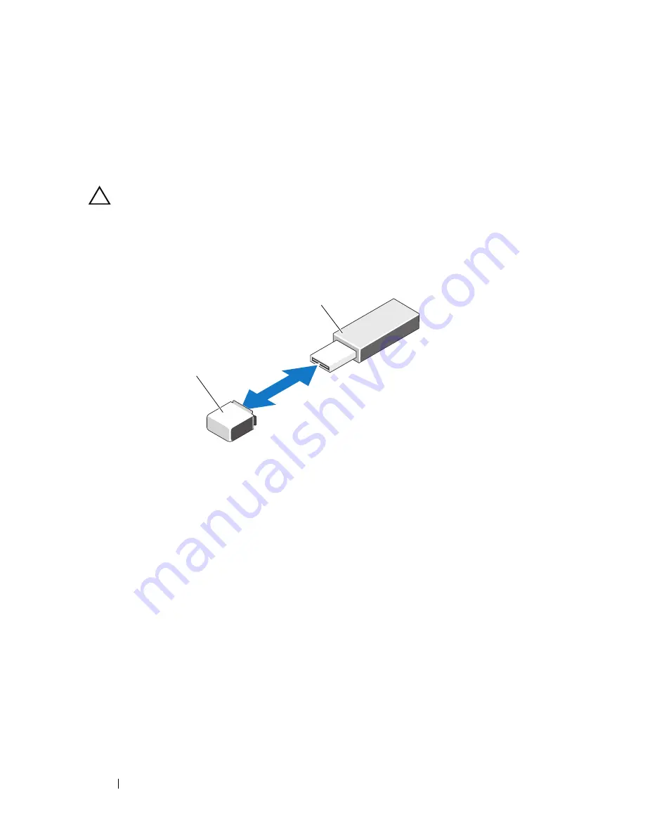
Figure 3-32. Installing a USB Memory Key
iDRAC6 Enterprise Card
Installing an iDRAC6 Enterprise Card
1
Remove the blade. See "Removing a Blade" on page 145.
2
Open the blade. See "Opening the Blade" on page 149.
3
Install the iDRAC6 Enterprise card:
a
Lower the card into place until the card connector fits into the
corresponding connector on the system board. See Figure 3-33.
b
Secure the card with the two Torx screws.
1
USB memory key connector on
system board (M710/M910) or
backplane (M710HD, M610, and
M610x)
2
USB memory key
1
2
Summary of Contents for PowerEdge M1000e
Page 1: ...Dell PowerEdge Modular Systems Hardware Owner s Manual ...
Page 56: ...56 About Your System Figure 1 21 Example of M610x Blade Port Mapping of Blade 2 ...
Page 64: ...64 About Your System Figure 1 23 Example of Half Height Blade Port Mapping ...
Page 126: ...126 About Your System ...
Page 144: ...144 Using the System Setup Program and UEFI Boot Manager ...
Page 264: ...264 Installing Blade Components ...
Page 286: ...286 Installing Enclosure Components ...
Page 308: ...308 Running System Diagnostics ...
Page 336: ...336 System Board Information ...
Page 338: ...338 Getting Help ...
Page 344: ...Index 344 V video controller installing 252 ...
Page 345: ...Index 345 ...
Page 346: ...346 Index ...


