12
Rack Installation Guide
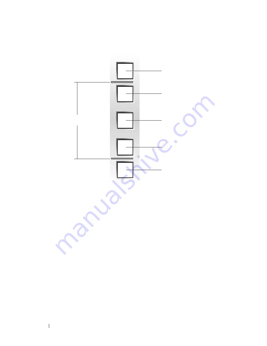
Figure 1-3.
One Rack Unit
2
Mark the rack’s front vertical rails with a felt-tipped pen or masking tape
approximately 44.45 cm (17.5 inches) above the original mark you made
(or count up 30 holes in a rack that meets CEA-310-E standards).
(If you counted holes, place a mark just above the top hole.) This mark
or piece of tape indicates where the system’s upper edge will be located
on the vertical rails (see Figure 1-4).
1 U (44 mm or 1.75 inches)
12.7 mm (0.5 inch)
15.9 mm (0.625 inch)
15.9 mm (0.625 inch)
12.7 mm (0.5 inch)
Summary of Contents for PowerEdge M1000e
Page 2: ......
Page 3: ...Rack Installation Guide ...
Page 6: ...4 Contents ...
Page 15: ...Rack Installation Guide 13 Figure 1 4 Marking the Vertical Rails 1 tape on vertical rails 1 ...
Page 29: ...Guide d installation du rack ...
Page 32: ...30 Sommaire ...
Page 54: ...52 Guide d installation du rack ...
Page 57: ...Rack Installations anleitung ...
Page 60: ...58 Inhalt ...
Page 84: ...82 Rack Installationsanleitung ...
Page 87: ...ラック取り付けガイド ...
Page 90: ...88 目次 ...
Page 105: ...ラック取り付けガイド 103 図 1 7 ラックへのシステムの取り付け 1 蝶ネジ 4 2 LCD モジュール 3 レールアセンブリ 2 3 2 1 ...
Page 111: ...ラック取り付けガイド 109 ラック扉の取り付け ラックキャビネットに付属のマニュアルに記載されている扉の取り付け手 順を参照してください これでラックへのシステムの取り付けは完了です ...
Page 112: ...110 ラック取り付けガイド ...
Page 115: ...Guía de instalación del rack ...
Page 118: ...116 Contenido ...
Page 142: ...140 Guía de instalación del rack ...


