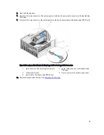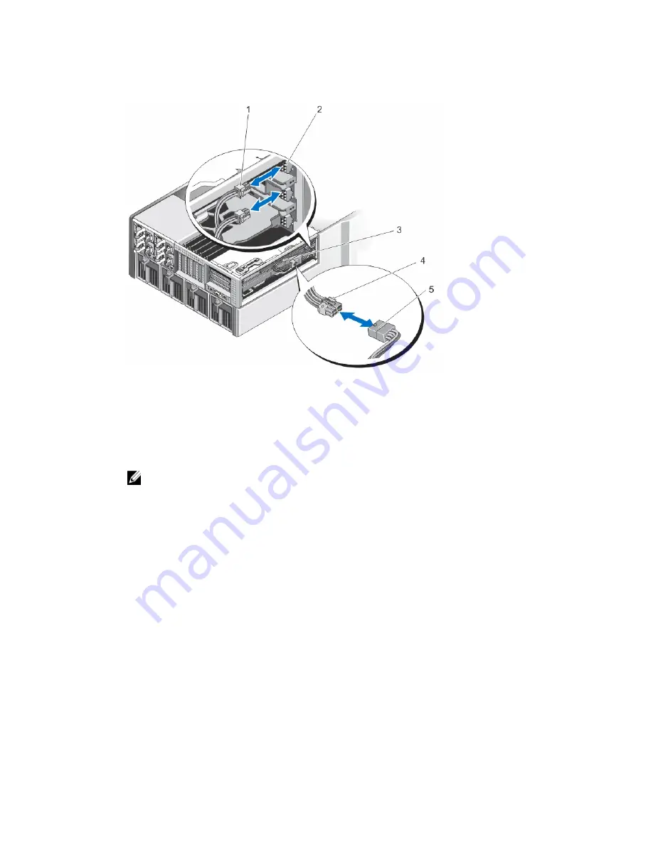
15. Connect the two 6-pin connectors on the other end of the auxiliary power cable to the power cable connectors on
the double-wide PCIe cage.
Figure 69. Installing the Auxiliary Power Cable to the Power Cable Connectors
1.
6-pin connector of the auxiliary power cable (2)
2.
power cable connectors on the double-wide
PCIe cage
3.
auxiliary power cable
4.
8-pin connector of the auxiliary power cable
5.
power cable of the double-wide GPGPU card
16. Close the PCIe cage door.
NOTE: Route the auxiliary power cables properly inside the double-wide PCIe cage to prevent them from
being pinched or crimped.
17. Close the system.
18. If applicable, place the system upright on a flat, stable surface and rotate the system feet outward.
19. If removed, reinstall the hard drives, server modules, and power supplies.
20. Reconnect the enclosure to its electrical outlet and turn the enclosure on, including any attached peripherals.
21. Turn on the server modules using the operating system commands or the CMC.
22. If applicable, install the front bezel.
23. Map the double-wide GPGPU card to the server module using the CMC (if not already mapped).
Integrated Storage Controller Cards
Your system includes two dedicated expansion-card slots on the system board for up to two integrated controller cards
that provide the integrated storage subsystem for the internal hard drives in your system.
The storage controllers support SAS hard drives and also enable you to set up the hard drives in RAID configurations as
supported by the version of the controllers included with your system.
103
Summary of Contents for PowerEdge M520
Page 1: ...Dell PowerEdge VRTX Enclosure Owner s Manual Regulatory Model E22S Regulatory Type E22S001 ...
Page 8: ...8 ...
Page 34: ...34 ...
Page 66: ...Figure 45 Securing the Power Cable Without Wheel Assembly 1 power cable 2 strap 66 ...
Page 148: ...148 ...
Page 151: ...Figure 94 System Board Connectors Back 1 midplane planar connectors 3 151 ...
Page 152: ...152 ...
Page 158: ...158 ...


