4
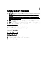
Installing Enclosure Components
WARNING: Whenever you need to lift the system, get others to assist you. To avoid injury, do not attempt to lift the
system by yourself.
WARNING: Exercise care when removing or installing components when the system is on, to avoid the risk of
electric shock.
CAUTION: To maintain optimum thermal conditions, ensure that there are no obstructions to airflow on the front
and back of the enclosure. The front and back of the enclosure must have at least 30 cm (12 inches) and 61 cm (24
inches) of unobstructed space respectively.
NOTE: To ensure proper operation and cooling, all bays in the enclosure must be populated at all times with either
a module or with a blank.
NOTE: It is recommended that you remove the front bezel, server modules, hard drives, and power supplies from
the chassis to reduce weight, before laying the enclosure on its side.
Recommended Tools
You may need the following items to perform the procedures in this section:
•
#1 and #2 Phillips screwdrivers
•
T6, T8, T10, T15, and T20 Torx drivers
•
Wrist grounding strap
Front Bezel (Optional)
Installing The Front Bezel
1.
Insert the bezel tabs into the bezel tab slots in the chassis.
2.
Press the top end of the bezel into the chassis until the bezel locks into place.
3.
Insert the bezel key in the keylock.
41
Summary of Contents for PowerEdge M520
Page 1: ...Dell PowerEdge VRTX Enclosure Owner s Manual Regulatory Model E22S Regulatory Type E22S001 ...
Page 8: ...8 ...
Page 34: ...34 ...
Page 66: ...Figure 45 Securing the Power Cable Without Wheel Assembly 1 power cable 2 strap 66 ...
Page 148: ...148 ...
Page 151: ...Figure 94 System Board Connectors Back 1 midplane planar connectors 3 151 ...
Page 152: ...152 ...
Page 158: ...158 ...


