4.
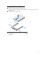
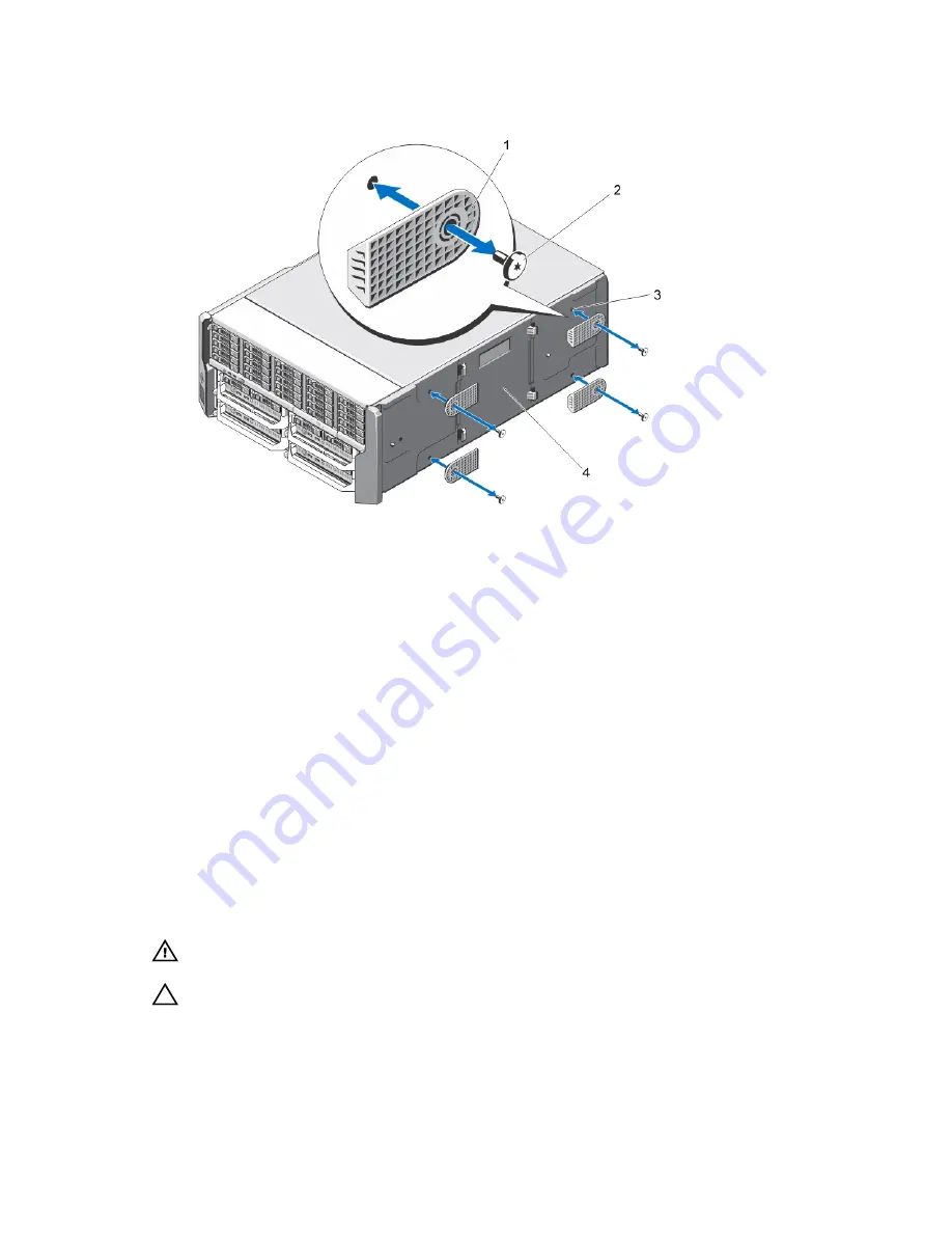
Remove the screws securing the system feet to the system base cover.
Figure 26. Removing and Installing the System Feet
1.
system feet (4)
2.
screws (4)
3.
screw holes (4)
4.
system base cover
Installing The System Feet
1.
Align the screw holes on the system feet with the screw holes on the system base cover.
2.
Install the screws to secure the system feet to the system base cover.
3.
Place the enclosure upright on a flat, stable surface and rotate the system feet outward.
4.
If removed, reinstall the hard drives, server modules, power supplies, and front bezel.
Wheel Assembly (Optional)—Tower Mode
The wheel assembly provides mobility to the system in the tower mode.
The wheel assembly consists of the following:
•
Wheel assembly units (front and back)
•
Power cable retention bracket
Installing The Wheel Assembly
WARNING: Whenever you need to lift the system, get others to assist you. To avoid injury, do not attempt to lift the
system by yourself.
CAUTION: Rolling the system on its wheels can cause vibrations that can damage the system.
43
Summary of Contents for PowerEdge M520
Page 1: ...Dell PowerEdge VRTX Enclosure Owner s Manual Regulatory Model E22S Regulatory Type E22S001 ...
Page 8: ...8 ...
Page 34: ...34 ...
Page 66: ...Figure 45 Securing the Power Cable Without Wheel Assembly 1 power cable 2 strap 66 ...
Page 148: ...148 ...
Page 151: ...Figure 94 System Board Connectors Back 1 midplane planar connectors 3 151 ...
Page 152: ...152 ...
Page 158: ...158 ...

