200
Installing Blade Components
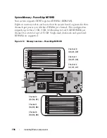
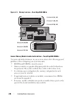
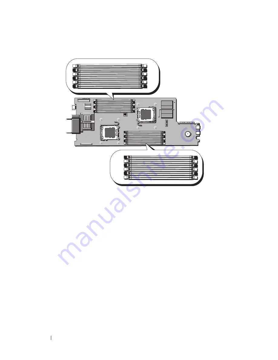
Figure 3-19. Memory Locations
–
PowerEdge M610/M610x
General Memory Module Installation Guidelines – PowerEdge M610/M610x
To ensure optimal performance of your system, observe the following general
guidelines when configuring your system memory:
• RDIMMs and UDIMMs cannot be mixed.
• Memory modules are populated beginning with the socket farthest from
the processor (this socket is indicated by a white socket-release lever).
• In a dual-processor configuration, the memory configuration for each
processor must be identical
• If quad-rank memory modules are installed, a maximum of two DIMMs
per channel is supported.
• If memory modules with different speeds are installed, they operate at the
speed of the slowest installed memory modules.
A1
A4
A2
A5
A3
A6
B6
B3
B5
B2
B4
B1
Channel 2 (A1, A4)
Channel 1 (A2, A5)
Channel 0 (A3, A6)
Channel 0 (B3, B6)
Channel 1 (B2, B5)
Channel 2 (B1, B4)
CPU1
CPU2
Summary of Contents for PowerEdge M620
Page 1: ...Dell PowerEdge Modular Systems Hardware Owner s Manual ...
Page 60: ...60 About Your System Figure 1 24 Example of PowerEdge M610x Port Mapping of Blade 2 ...
Page 68: ...68 About Your System Figure 1 26 Example of Half Height Blade Port Mapping ...
Page 136: ...136 About Your System ...
Page 286: ...286 Installing Blade Components ...
Page 308: ...308 Installing Enclosure Components ...
Page 330: ...330 Running System Diagnostics ...
Page 360: ...360 System Board Information ...
Page 362: ...362 Getting Help ...
Page 368: ...Index 368 V video controller installing 273 ...


