System Board Information
343
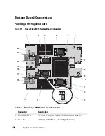
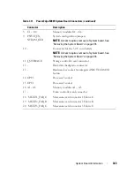
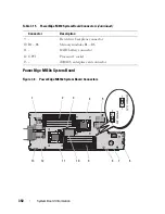
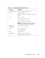
8 C1 – C4
Memory modules C1 – C4
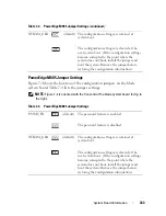
9 PSWD_EN,
NVRAM_CLR
System configuration jumpers
NOTE:
Access requires removal of system board. See
"Removing the System Board" on page 276.
10 -
Connector for the 3.0 V coin battery
NOTE:
Access requires removal of system board. See
"Removing the System Board" on page 276.
11 J_STORAGE
Storage controller card connector
12 -
Hard-drive backplane connector
13 -
Hardware key socket for integrated NIC TOE/iSCSI
feature
14 CPU3
Processor 3 socket
15 CPU1
Processor 1 socket
16 A1 – A8
Memory modules A1 – A8
17 -
Video controller card connector
18 MEZZ1_FAB_C
Mezzanine card connector 1 Fabric C
19 MEZZ2_FAB_B
Mezzanine card connector 2 Fabric B
20 MEZZ3_FAB_C
Mezzanine card connector 3 Fabric C
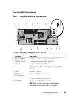
Table 7-11. PowerEdge M905 System Board Connectors
(continued)
Connector
Description
Summary of Contents for PowerEdge M620
Page 1: ...Dell PowerEdge Modular Systems Hardware Owner s Manual ...
Page 60: ...60 About Your System Figure 1 24 Example of PowerEdge M610x Port Mapping of Blade 2 ...
Page 68: ...68 About Your System Figure 1 26 Example of Half Height Blade Port Mapping ...
Page 136: ...136 About Your System ...
Page 286: ...286 Installing Blade Components ...
Page 308: ...308 Installing Enclosure Components ...
Page 330: ...330 Running System Diagnostics ...
Page 360: ...360 System Board Information ...
Page 362: ...362 Getting Help ...
Page 368: ...Index 368 V video controller installing 273 ...

