About Your System
49
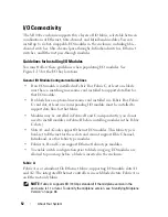
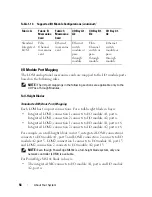
The CMC provides multiple systems management functions for your
modular server:
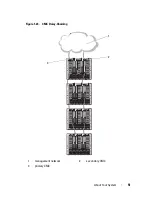
• Enclosure-level real-time automatic power and thermal management.
–
The CMC monitors system power requirements and supports the
optional Dynamic Power Supply Engagement mode so that the CMC
can enable or place power supplies in standby dynamically depending
on load and redundancy requirements to improve power efficiency.
–
The CMC reports real-time power consumption, which includes
logging high and low points with a time stamp.
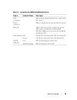
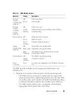
Table 1-11. CMC Module Features
Indicator
Pattern
Description
Network
interface
controller link
indicator
Off
LAN is not linked.
Green
LAN is linked.
Network
interface
controller
activity
indicator
Off
LAN is not active.
Amber
blinking
Indicates that the system CMC and the LAN are
communicating.
Power indicator Off
CMC does not have power.
Green
CMC has power.
Green
blinking
Firmware update in progress.
Status/
identification
indicator
Off
This CMC is the standby CMC.
Blue (solid) This CMC is the primary CMC.
Blue
(blinking)
The CMC is being identified by the systems
management software.
Fault indicator Off
The CMC is operating normally.
Amber
blinking
A fault has occurred.
Serial
connector
None
Used for local configuration (115200 baud, No parity,
8, 1)
Summary of Contents for PowerEdge M620
Page 1: ...Dell PowerEdge Modular Systems Hardware Owner s Manual ...
Page 60: ...60 About Your System Figure 1 24 Example of PowerEdge M610x Port Mapping of Blade 2 ...
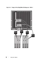
Page 68: ...68 About Your System Figure 1 26 Example of Half Height Blade Port Mapping ...
Page 136: ...136 About Your System ...
Page 286: ...286 Installing Blade Components ...
Page 308: ...308 Installing Enclosure Components ...
Page 330: ...330 Running System Diagnostics ...
Page 360: ...360 System Board Information ...
Page 362: ...362 Getting Help ...
Page 368: ...Index 368 V video controller installing 273 ...

