52
About Your System
I/O Connectivity
The M1000e enclosure supports three layers of I/O fabric, selectable between
combinations of Ethernet, fibre-channel, and Infiniband modules. You can
install up to six hot-swappable I/O modules in the enclosure, including fibre-
channel switches, fibre-channel pass-throughs, Infiniband switches, Ethernet
switches, and Ethernet pass-through modules.
Guidelines for Installing I/O Modules
You must follow these guidelines when populating I/O modules. See
Figure 1-15 for the I/O bay locations.
General I/O Module Configuration Guidelines
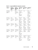
• If an I/O module is installed in Fabric B or Fabric C, at least one blade
must have a matching mezzanine card installed to support data flow for
that I/O module.
• If a blade has an optional mezzanine card installed in a Fabric B or Fabric
C card slot, at least one corresponding I/O module must be installed to
support data flow for that fabric.
• Modules may be installed in Fabrics B and C independently (you do not
need to install modules in Fabric B before installing modules in the Fabric
C slots.)
• Slots A1 and A2 only support Ethernet I/O modules. This fabric type is
hard-set to Ethernet for these slots and cannot support Fibre Channel,
Infiniband, or other fabric type modules.
• Fabrics A, B, and C can support Ethernet fabric-type modules.
• To enable switch configuration prior to blade imaging, I/O modules are
allowed to power-up before a blade is inserted in the enclosure.
Fabric A
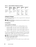
Fabric A is a redundant Gb Ethernet fabric, supporting I/O module slots A1
and A2. The integrated Ethernet controllers in each blade dictate Fabric A as
an Ethernet-only fabric.
NOTE:
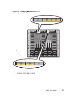
Fabric A supports KR (10 Gbps standard) if the midplane version in the
enclosure is 1.1 or later. To identify the midplane version, see "Identifying Midplane
Version" on page 38.
Summary of Contents for PowerEdge M620
Page 1: ...Dell PowerEdge Modular Systems Hardware Owner s Manual ...
Page 60: ...60 About Your System Figure 1 24 Example of PowerEdge M610x Port Mapping of Blade 2 ...
Page 68: ...68 About Your System Figure 1 26 Example of Half Height Blade Port Mapping ...
Page 136: ...136 About Your System ...
Page 286: ...286 Installing Blade Components ...
Page 308: ...308 Installing Enclosure Components ...
Page 330: ...330 Running System Diagnostics ...
Page 360: ...360 System Board Information ...
Page 362: ...362 Getting Help ...
Page 368: ...Index 368 V video controller installing 273 ...


