background image

1

About Your System

Front-Panel Features And Indicators

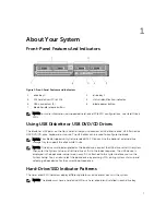
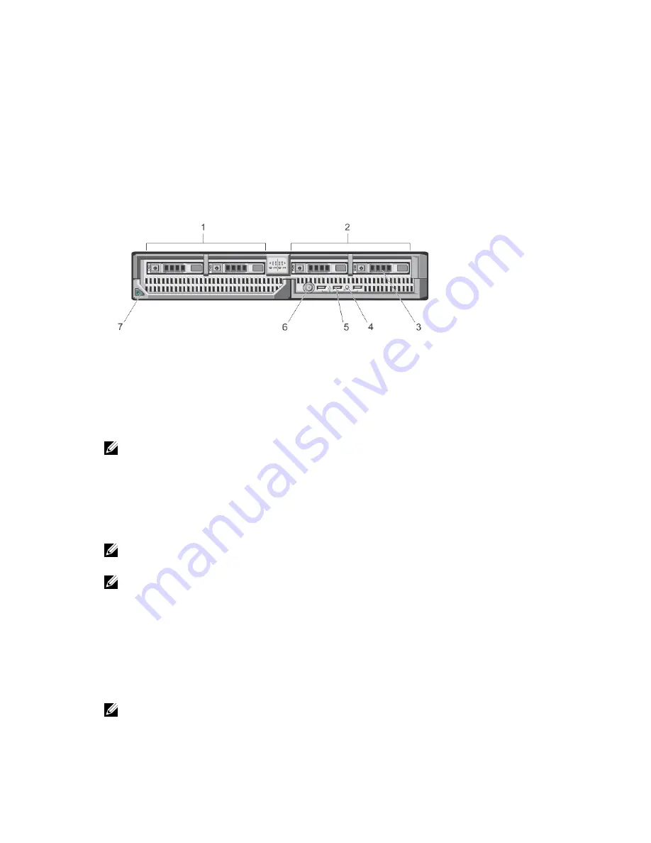
Figure 1. Front-Panel Features and Indicators

1.

drive bay 0

2.

drive bay 1

3.

SAS hard drives/PCIe SSDs

4.

status/identification indicator

5.

USB connectors (3)

6.

blade power button

7.

blade handle release button

NOTE: For more information on supported hard-drive/PCIe SSD configurations, see Hard Drives/
SSDs.

Using USB Diskette or USB DVD/CD Drives

The blade has USB ports on the front which allow you to connect a USB diskette drive, USB flash drive, 
USB DVD/CD drive, keyboard, or mouse. The USB drives can be used to configure the blade.

NOTE: Your blade supports only Dell-branded USB 2.0 drives. Use the optional external drive 
storage tray to support the drive while in use.

NOTE: If the drive must be designated as the boot drive, connect the USB drive, restart the system, 
then enter the System Setup and set the drive as first in the boot sequence. The USB device is 
displayed in the boot order setup screen only if it is attached to the system before you run the 
System Setup. You can also select the boot device by pressing <F11> during system start-up and 
selecting a boot device for the current boot sequence.

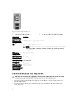
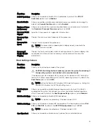
Hard-Drive/SSD Indicator Patterns

The hard-drive/SSD indicators display different patterns as drive events occur in the system.

NOTE: The blade must have a hard drive/SSD or a hard-drive blank installed in each drive bay.

7

Summary of Contents for PowerEdge M820 Systems

Page 1: ...Dell PowerEdge M820 Systems Owner s Manual Regulatory Model FHB Regulatory Type FHB007 ...

Page 2: ...problem WARNING A WARNING indicates a potential for property damage personal injury or death Copyright 2014 Dell Inc All rights reserved This product is protected by U S and international copyright and intellectual property laws Dell and the Dell logo are trademarks of Dell Inc in the United States and or other jurisdictions All other marks and names mentioned herein may be trademarks of their res...

Page 3: ...Settings Screen 14 Boot Settings Screen 15 Integrated Devices Screen 16 Serial Communications Screen 17 System Profile Settings Screen 17 System Security Screen 18 Miscellaneous Settings 19 System And Setup Password Features 19 Assigning A System And Or Setup Password 20 Using Your System Password To Secure Your System 21 Deleting Or Changing An Existing System And Or Setup Password 21 Operating W...

Page 4: ...Carrier 33 Hard Drive SSD Backplane 34 Removing The Hard Drive SSD Backplane 34 Installing The Hard Drive SSD Backplane 36 I O Module Mezzanine Cards 37 Mezzanine Card Installation Guidelines 37 Removing A Mezzanine Card 37 Installing A Mezzanine Card 38 Network Daughter Card LOM Riser Card 39 Removing The Network Daughter Card LOM Riser Card 39 Installing The Network Daughter Card LOM Riser Card ...

Page 5: ...Drives 69 Troubleshooting USB Devices 69 Troubleshooting An Internal SD Card 70 Troubleshooting Processors 70 Troubleshooting The Blade System Board 71 Troubleshooting The NVRAM Backup Battery 71 5 Using System Diagnostics 72 Dell Online Diagnostics 72 Dell Embedded System Diagnostics 72 When To Use The Embedded System Diagnostics 72 Running The Embedded System Diagnostics 73 System Diagnostic Con...

Page 6: ...Alert Messages 154 9 Getting Help 155 Contacting Dell 155 ...

Page 7: ...E Your blade supports only Dell branded USB 2 0 drives Use the optional external drive storage tray to support the drive while in use NOTE If the drive must be designated as the boot drive connect the USB drive restart the system then enter the System Setup and set the drive as first in the boot sequence The USB device is displayed in the boot order setup screen only if it is attached to the syste...

Page 8: ...er and off Drive predicted failure Blinks amber four times per second Drive failed Blinks green slowly Drive rebuilding Steady green Drive online Blinks green three seconds amber three seconds and off six seconds Rebuild aborted Other Information You May Need WARNING See the safety and regulatory information that shipped with your system Warranty information may be included within this document or...

Page 9: ...document see the Glossary at www dell com support manuals Dell systems management application documentation provides information about installing and using the systems management software Any media that ships with your system that provides documentation and tools for configuring and managing your system including those pertaining to the operating system system management software system updates an...

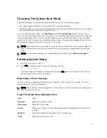
Page 10: ...OS Boot Manager or the Unified Extensible Firmware Interface UEFI Boot Manager depending on the system s boot configuration F12 Starts Preboot Execution Environment PXE boot From the System Setup you can Change the NVRAM settings after you add or remove hardware View the system hardware configuration Enable or disable integrated devices Set performance and power management thresholds Manage system...

Page 11: ...de DOS and 32 bit operating systems do not support UEFI and can only be installed from the BIOS boot mode NOTE For the latest information on supported operating systems go to dell com ossupport Entering System Setup 1 Turn on or restart your system 2 Press F2 immediately after you see the following message F2 System Setup If your operating system begins to load before you press F2 allow the system...

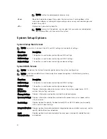
Page 12: ... based on the system configuration NOTE System Setup defaults are listed under their respective options in the following sections where applicable Menu Item Description iDRAC Settings This option is used to view and configure iDRAC settings Device Settings This option is used to view and configure device settings System Information Displays information about the system such as the system model nam...

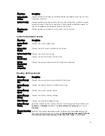
Page 13: ... name of system manufacturer System Manufacturer Contact Information Displays the contact information of the system manufacturer Memory Settings Screen Menu Item Description System Memory Size Displays the amount of memory installed in the system System Memory Type Displays the type of memory installed in the system System Memory Speed Displays the system memory speed System Memory Voltage Display...

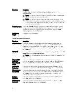
Page 14: ...ogical processor per core By default the Logical Processor option is set to Enabled QPI Speed Allows you to set the QuickPath Interconnect data rate settings By default the QPI Speed option is set to Maximum data rate NOTE The QPI Speed option is displayed only when both the processors are installed Alternate RTID Requestor Transaction ID Setting Allows you to allocate more RTIDs to the remote soc...

Page 15: ...t Mode Allows you to set the boot mode of the system CAUTION Switching the boot mode may prevent the system from booting if the operating system is not installed in the same boot mode If the operating system supports UEFI you can set this option to UEFI Setting this field to BIOS allows compatibility with non UEFI operating systems By default the Boot Mode option is set to BIOS NOTE Setting this f...

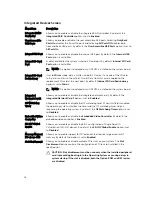
Page 16: ... installed on the system board Integrated Network Card 1 Allows you to enable or disable the integrated network card 1 By default the Integrated Network Card 1 option is set to Enabled OS Watchdog Timer Allows you to enable or disable the OS watchdog timer When this field is enabled the operating system initializes the timer and the OS watchdog timer helps in recovering the operating system By def...

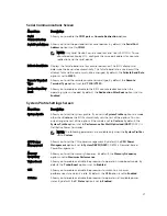
Page 17: ...bled System Profile Settings Screen Menu Item Description System Profile Allows you to set the system profile If you set the System Profile option to a mode other than Custom the BIOS automatically sets the rest of the options You can only change the rest of the options if the mode is set to Custom By default the System Profile option is set to Performance Per Watt Optimized DAPC DAPC is Dell Acti...

Page 18: ...m Password Allows you to set the system password This option is read only if the password jumper is not installed in the system Setup Password Allows you to set the setup password This option is read only if the password jumper is not installed in the system Password Status Allows you to lock the system password By default the Password Status option is set to Unlocked TPM Security Allows you to co...

Page 19: ...h the NumLock enabled or disabled By default the Keyboard NumLock is set to On NOTE This field does not apply to 84 key keyboards Report Keyboard Errors Allows you to set whether keyboard related error messages are reported during system boot By default the Report Keyboard Errors field is set to Report F1 F2 Prompt on Error Allows you to enable or disable the F1 F2 prompt on error By default F1 F2...

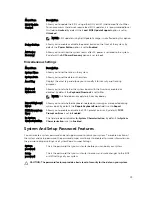
Page 20: ... power on or reboot 2 In the System Setup Main Menu select System BIOS and press Enter The System BIOS screen is displayed 3 In the System BIOS screen select System Security and press Enter The System Security screen is displayed 4 In the System Security screen verify that Password Status is Unlocked 5 Select System Password enter your system password and press Enter or Tab Use the following guide...

Page 21: ...r Setup password You cannot delete or change an existing System or Setup password if the Password Status is Locked To delete or change the existing System and or Setup password 1 To enter System Setup press F2 immediately after a power on or restart 2 In the System Setup Main Menu select System BIOS and press Enter The System BIOS screen is displayed 3 In the System BIOS Screen select System Secur...

Page 22: ... DOS and 32 bit operating systems can only be installed from the BIOS boot mode The Boot Manager enables you to Add delete and arrange boot options Access System Setup and BIOS level boot options without restarting To enter the Boot Manager 1 Turn on or restart your system 2 Press F11 after you see the following message F11 UEFI Boot Manager If your operating system begins to load before you press...

Page 23: ...tup Enables you to access the System Setup System Utilities Enables you to access the BIOS Update File Explorer run the Dell Diagnostics program and reboot the system UEFI Boot Menu Menu Item Description Select UEFI Boot Option Displays the list of available UEFI boot options marked with asterisks select the boot option you wish to use and press Enter Add Boot Option Adds a new boot option Delete ...

Page 24: ...he iDRAC Settings Utility requires the iDRAC7 Enterprise License upgrade For more information on using iDRAC see the iDRAC7 User s Guide under Software Systems Management Dell Remote Access Controllers at dell com support manuals Entering The iDRAC Settings Utility 1 Turn on or restart the managed system 2 Press F2 during Power on Self test POST 3 In the System Setup Main Menu page click iDRAC Set...

Page 25: ...ade using operating system commands or the CMC and ensure that the blade s power is off When a blade is powered off its front panel power indicator is off 2 Before removing the blades from full height blade slots 3 or 4 rotate the LCD panel to the storage position to prevent accidental damage to the LCD screen 3 Press the release button on the handle 4 Pull out the handle to unlock the blade from ...

Page 26: ...ave for future use 2 Orient the blade so that the handle is on the left side of the blade 3 If you are installing the full height blade in bays 3 or 4 rotate the LCD module to the horizontal storage position to prevent accidental damage to the LCD screen 4 Align the guide rail on the upper edge of the blade so that the rail fits between the plastic guides on the enclosure 5 Slide the blade into th...

Page 27: ...covered by your warranty Read and follow the safety instructions that came with the product NOTE It is recommended that you always use a static mat and static strap while working on components in the interior of the system 1 Remove the blade from the enclosure 2 Install the I O connector cover 3 Press the release buttons and slide the cover toward the back of the blade 4 Carefully lift the cover a...

Page 28: ...e of the chassis Inside The Blade CAUTION Many repairs may only be done by a certified service technician You should only perform troubleshooting and simple repairs as authorized in your product documentation or as directed by the online or telephone service and support team Damage due to servicing that is not authorized by Dell is not covered by your warranty Read and follow the safety instructio...

Page 29: ...only be done by a certified service technician You should only perform troubleshooting and simple repairs as authorized in your product documentation or as directed by the online or telephone service and support team Damage due to servicing that is not authorized by Dell is not covered by your warranty Read and follow the safety instructions that came with the product CAUTION Never operate your sy...

Page 30: ...safety instructions that came with the product 1 Align the tabs on the cooling shroud with the slots on the chassis 2 Lower the cooling shroud into the system until the tabs seat securely on the slots on the blade chassis 3 Close the blade 4 Install the blade in the enclosure Hard Drives SSDs The system supports up to four 2 5 inch SAS hard drives or two PCIe SSDs All drives connect to the system ...

Page 31: ...ed on the system board connector labeled J_BP1 NOTE To locate J_BP0 J_BP1 MiniPERC CARD and the PCIe EXTENDER connectors on the system board see System Board Connectors Removing A Hard Drive PCIe SSD CAUTION Many repairs may only be done by a certified service technician You should only perform troubleshooting and simple repairs as authorized in your product documentation or as directed by the onl...

Page 32: ...d with your operating system 1 Open the hard drive PCIe SSD carrier handle 2 Insert the hard drive PCIe SSD carrier into the drive bay Align the channel on the hard drive PCIe SSD carrier with the appropriate drive slot on the blade 3 Push the hard drive PCIe SSD carrier into the slot until the carrier connects with the hard drive PCIe SSD backplane 4 Rotate the hard drive PCIe SSD handle to the c...

Page 33: ... the hard drive PCIe SSD carrier Figure 8 Removing and Installing a Hard Drive PCIe SSD in a Hard Drive PCIe SSD Carrier 1 hard drive PCIe SSD 2 screw holes 4 3 hard drive PCIe SSD carrier 4 screws 4 Installing A Hard Drive PCIe SSD In A Hard Drive PCIe SSD Carrier 1 Insert the hard drive PCIe SSD into the hard drive PCIe SSD carrier with the drive s controller board s connector end of the drive a...

Page 34: ...bleshooting and simple repairs as authorized in your product documentation or as directed by the online or telephone service and support team Damage due to servicing that is not authorized by Dell is not covered by your warranty Read and follow the safety instructions that came with the product 1 Remove the blade from the enclosure 2 Open the blade CAUTION You must note the number of each hard dri...

Page 35: ...Figure 9 Removing and Installing the Hard Drive SSD Backplane Full Length 1 guide pins 6 2 backplane connectors 2 3 hard drive SSD backplane 4 hard drive SSD connectors 4 5 guides 6 35 ...

Page 36: ...he Hard Drive SSD Backplane 1 Remove the blade from the enclosure 2 Open the blade 3 Align the guides on the hard drive SSD backplane with the guide pins on the system board 4 Press down the backplane until the connectors on the backplane and the system board are fully engaged 5 Install the hard drives SSDs in their original locations 6 Close the blade 7 Install the blade in the enclosure 36 ...

Page 37: ...B2 The blade supports SFF mezzanine cards x8 PCIe Gen 3 cards are supported Removing A Mezzanine Card CAUTION Many repairs may only be done by a certified service technician You should only perform troubleshooting and simple repairs as authorized in your product documentation or as directed by the online or telephone service and support team Damage due to servicing that is not authorized by Dell i...

Page 38: ...ty instructions that came with the product 1 Remove the blade from the enclosure 2 Open the blade 3 Open the retention latch by pressing the ridged area on the latch with your thumb and lifting the end of the latch 4 If present remove the connector cover from the mezzanine card bay NOTE Hold the mezzanine card by its edges only 5 Mezzanine cards are designed to fit in either card slot Rotate the c...

Page 39: ...is not authorized by Dell is not covered by your warranty Read and follow the safety instructions that came with the product 1 Remove the blade from the enclosure 2 Open the blade 3 Remove the two screws that secure the Network Daughter Card LOM riser card to the system board 4 Lift the card from the system board 5 Close the blade 6 Install the blade in the enclosure Figure 12 Removing and Install...

Page 40: ...al SD interface maintains a mirrored configuration using SD cards in both slots and provides redundancy Single card operation single card operation is supported but without redundancy Replacing The SD Card NOTE The SD card in the lower card slot is the primary card SD1 and the SD card in the upper card slot is the secondary card SD2 1 Enter the System Setup and ensure that the Internal SD Card Por...

Page 41: ...creating a bootable file on the USB memory key see the user documentation that accompanied the USB memory key Replacing The Internal USB Key CAUTION Many repairs may only be done by a certified service technician You should only perform troubleshooting and simple repairs as authorized in your product documentation or as directed by the online or telephone service and support team Damage due to ser...

Page 42: ...blade from the enclosure 2 If installed remove the SD vFlash card from the card slot NOTE The SD vFlash card slot is located underneath LOM riser card 1 and can be identified by the SD vFlash card slot identification label 3 To install the SD vFlash card insert the contact pin end of the SD card into the card slot on the vFlash media unit with the card label side facing up NOTE The slot is keyed t...

Page 43: ... processor you must install a socket protective cap and a processor DIMM blank in the vacant socket to ensure proper system cooling The processor DIMM blank covers the vacant sockets for the DIMMs and the processor Removing A Processor DIMM Blank 1 Remove the blade from the enclosure 2 Open the blade 3 Remove the cooling shroud 4 Lift the processor DIMM blank away from the system 43 ...

Page 44: ...lank 1 Remove the blade from the enclosure 2 Open the blade 3 If installed remove the processor and heat sink 4 Position the processor DIMM blank on the system board with the holes on the tabs of the processor DIMM blank secured to the heat sink retention screws on the system board 5 Install the cooling shroud 6 Close the blade 7 Install the blade in the enclosure 44 ...

Page 45: ...zed in your product documentation or as directed by the online or telephone service and support team Damage due to servicing that is not authorized by Dell is not covered by your warranty Read and follow the safety instructions that came with the product 1 Remove the blade from the enclosure 2 Open the blade WARNING The processor and heat sink can become extremely hot Be sure the processor has had...

Page 46: ... under strong pressure Be aware that the release lever can spring up suddenly if not firmly grasped 7 Position your thumb firmly over the socket release lever near the label marked OPEN 1st and release the lever from the locked position by pushing down and out from under the tab Rotate the socket release lever upward 8 Similarly release the socket release lever near the label marked CLOSE 1st from...

Page 47: ...t you install remove the socket protective cap from the processor shield with the processor shield in the open position CAUTION The socket pins are fragile and can be permanently damaged Be careful not to bend the pins in the socket when removing the processor out of the socket 11 Lift the processor out of the socket and leave the release lever up so that the socket is ready for the new processor ...

Page 48: ...Removing and Installing a Processor 1 socket release lever 2 2 pin 1 corner of processor 3 tabs 2 4 processor shield 5 socket protective cap 6 socket release lever 1 7 pin 1 corner on system board 8 processor 48 ...

Page 49: ...rocessor is positioned correctly it engages easily into the socket 5 Install the processor in the socket a Identify the pin 1 corner of the processor by locating the tiny gold triangle on one corner of the processor Place this corner in the same corner of the ZIF socket identified by a corresponding triangle on the system board b Align the pin 1 corner of the processor with the pin 1 corner of the...

Page 50: ... the blade from the enclosure 2 Open the blade 3 Install an I O connector cover on the I O connector s at the back of the board WARNING The processor and heat sink can become extremely hot Be sure the processor has had sufficient time to cool before handling WARNING The memory modules are hot to the touch for some time after the system has been powered down Allow time for the memory modules to coo...

Page 51: ...nd heat sinks or processor DIMM blanks memory modules and memory module blanks CAUTION Ensure that the system board plate is parallel with the chassis 2 Slide the new system board into the open end of the blade chassis until the retention latch engages When the board assembly is installed correctly the tabs on the system board pan snap into the corresponding openings in the floor of the blade chas...

Page 52: ...ond Memory bus operating frequency can be either 800 MT s 1066 MT s 1333 MT s or 1600 MT s depending on the DIMM type RDIMM or LRDIMM DIMM configuration number of ranks Maximum frequency of the DIMMs Number of DIMMs populated per channel DIMM operating voltage System profile selected for example Performance Optimized Custom or Dense Configuration Optimized Maximum supported DIMM frequency of the p...

Page 53: ...ockets A1 A5 and A9 channel 1 memory sockets A2 A6 and A10 channel 2 memory sockets A3 A7 and A11 channel 3 memory sockets A4 A8 and A12 Processor 2 channel 0 memory sockets B1 B5 and B9 channel 1 memory sockets B2 B6 and B10 channel 2 memory sockets B3 B7 and B11 channel 3 memory sockets B4 B8 and B12 53 ...

Page 54: ...Channel 1 5 V 1 35 V Intel Xeon Processor E5 4600 RDIMM 1 1600 1333 1066 and 800 1333 1066 and 800 Dual rank 1333 1066 and 800 1066 and 800 Quad rank 2 1600 1333 1066 and 800 1333 1066 and 800 Dual rank 1066 and 800 1066 and 800 Quad rank 3 1333 1066 and 800 1066 and 800 Dual rank LRDIMM 1 1333 and 1066 1333 and 1066 Quad rank 2 1333 and 1066 1333 and 1066 Quad rank 3 1066 1066 Quad rank Intel Xeo...

Page 55: ...12 are available For four processor systems sockets A1 to A12 B1 to B12 C1 to C12 and D1 to D12 are available Populate the sockets by highest rank count in the following order first in sockets with white release levers then black and then green For example to mix quad rank and dual rank DIMMs populate quad rank DIMMs in the sockets with white release tabs and dual rank DIMMs in the sockets with bl...

Page 56: ...MMs require Advanced ECC mode to gain SDDC The following sections provide additional slot population guidelines for each mode Advanced ECC Lockstep Advanced ECC mode extends SDDC from x4 DRAM based DIMMs to both x4 and x8 DRAMs This protects against single DRAM chip failures during normal operation Memory installation guidelines Memory modules must be identical in size speed and technology DIMMs i...

Page 57: ...nsures SDDC and multi bit protection Memory installation guidelines Memory modules must be identical in size speed and technology DIMMs installed in memory sockets with white release tabs must be identical and similar rule applies for sockets with black and green release tabs This ensures that identical DIMMs are installed in matched pairs for example A1 with A2 A3 with A4 A5 with A6 and so on Sam...

Page 58: ... B6 128 8 16 2R x4 1333 MT s 2R x4 1600 MT s A1 A2 A3 A4 A5 A6 A7 A8 B1 B2 B3 B4 B5 B6 B7 B8 128 16 8 2R x4 1333 MT s 2R x4 1600 MT s A1 A2 A3 A4 B1 B2 B3 B4 160 8 20 2R x4 1333 MT s 2R x4 1600 MT s A1 A2 A3 A4 A5 A6 A7 A8 A9 A10 B1 B2 B3 B4 B5 B6 B7 B8 B9 B10 160 16 and 8 12 2R x4 1333 MT s 2R x4 1600 MT s A1 A2 A3 A4 A5 A6 B1 B2 B3 B4 B5 B6 NOTE 16 GB DIMMs must be installed in the slots numbere...

Page 59: ...ory Configurations Four Processors System Capacity in GB DIMM Size in GB Number of DIMMs Organization and Speed DIMM Slot Population 8 2 4 1R x8 1333 MT s 1R x8 1600 MT s A1 B1 C1 D1 16 2 8 1R x8 1333 MT s 1R x8 1600 MT s A1 A2 B1 B2 C1 C2 D1 D2 24 2 12 1R x8 1333 MT s 1R x8 1600 MT s A1 A2 A3 B1 B2 B3 C1 C2 C3 D1 D2 D3 40 2 20 1R x8 1333 MT s 1R x8 1600 MT s A1 A2 A3 A4 A5 B1 B2 B3 B4 B5 C1 C2 C3...

Page 60: ...0 MT s A1 A2 A3 A4 B1 B2 B3 B4 C1 C2 C3 C4 D1 D2 D3 D4 192 4 48 2R x4 1333 MT s 2R x4 1600 MT s A1 A2 A3 A4 A5 A6 A7 A8 A9 A10 A11 A12 B1 B2 B3 B4 B5 B6 B7 B8 B9 B10 B11 B12 C1 C2 C3 C4 C5 C6 C7 C8 C9 C10 C11 C12 D1 D2 D3 D4 D5 D6 D7 D8 D9 D10 D11 D12 192 8 24 2R x4 1333 MT s 2R x4 1600 MT s A1 A2 A3 A4 A5 A6 B1 B2 B3 B4 B5 B6 C1 C2 C3 C4 C5 C6 D1 D2 D3 D4 D5 D6 256 16 16 2R x4 1333 MT s 2R x4 160...

Page 61: ...t is not authorized by Dell is not covered by your warranty Read and follow the safety instructions that came with the product CAUTION To ensure proper system cooling memory module blanks must be installed in any memory socket that is not occupied Remove memory module blanks only if you intend to install memory modules in those sockets CAUTION If you are permanently removing a processor you must i...

Page 62: ...dule CAUTION Many repairs may only be done by a certified service technician You should only perform troubleshooting and simple repairs as authorized in your product documentation or as directed by the online or telephone service and support team Damage due to servicing that is not authorized by Dell is not covered by your warranty Read and follow the safety instructions that came with the product...

Page 63: ...s on the memory module socket align with the ejectors on the other sockets that have memory modules installed 10 Repeat step 5 through step 7 of this procedure to install the remaining memory modules 11 If applicable install the following a system board b mezzanine card s c SSD hard drive backplane s 12 If applicable close the latch on the mezzanine card support bracket 13 Install the cooling shro...

Page 64: ...itive side of the connector 6 Press the battery straight down into the connector until it snaps into place 7 Reinstall the system board 8 Close the blade 9 Install the blade in the enclosure 10 Enter the System Setup to confirm that the battery is operating properly 11 Enter the correct time and date in the System Setup s Time and Date fields 12 Exit the System Setup 13 To test the newly installed...

Page 65: ...uct documentation or as directed by the online or telephone service and support team Damage due to servicing that is not authorized by Dell is not covered by your warranty Read and follow the safety instructions that came with the product CAUTION To ensure proper system cooling a storage controller blank must be installed on the storage controller card PCIe extender card connector that is not occu...

Page 66: ...Figure 24 Removing and Installing a Storage Controller Card 1 screws 2 2 storage controller card 3 tabs 2 4 connector 66 ...

Page 67: ...he other end of the card so that the card edge is secured to the bracket When correctly seated the storage controller card is secured under the tabs on the support bracket the notch on the PCIe extender card is securely aligned with the corresponding tab on the support bracket 3 Insert the card connector firmly into the system board connector until the card is fully seated 4 Install the two screws...

Page 68: ... to servicing that is not authorized by Dell is not covered by your warranty Read and follow the safety instructions that came with the product NOTE Before performing the following procedure ensure that you have installed the memory modules according to the memory installation guidelines for the blade 1 Restart the blade a Press the power button once to turn off the blade b Press the power button ...

Page 69: ...irror if the mirror state is optimal 5 Remove the hard drive and install it in the other drive bay 6 If the problem is resolved reinstall the hard drive in the original bay If the hard drive functions properly in the original bay the drive carrier could have intermittent problems Replace the drive carrier 7 If the hard drive is the boot drive ensure that the drive is configured and connected prope...

Page 70: ...into SD card slot 1 c Install a new SD card in slot 2 5 If the Internal SD Card Redundancy option in the Integrated Devices screen of the System Setup is set to Mirror mode and SD card 2 has failed insert the new SD card into SD card slot 2 6 If the Internal SD Card Redundancy option in Integrated Devices screen of the System Setup is set to Disabled replace the failed SD card with a new SD card 7...

Page 71: ...d follow the safety instructions that came with the product The battery maintains the blade configuration date and time information in the NVRAM when the blade is turned off You may need to replace the battery if an incorrect time or date is displayed during the boot routine You can operate the blade without a battery however the blade configuration information maintained by the battery in NVRAM i...

Page 72: ...rface GUI or the command line interface CLI to run diagnostic tests on the hardware that Online Diagnostics discovers on your system For information about using diagnostics see the Dell Online PowerEdge Diagnostics User s Guide under Software Serviceability Tools at dell com support manuals Dell Embedded System Diagnostics NOTE Also known as Enhanced Pre boot System Assessment ePSA diagnostics The...

Page 73: ...ll devices detected in the system The diagnostics starts executing the tests on all the detected devices System Diagnostic Controls Menu Description Configuration Displays the configuration and status information of all detected devices Results Displays the results of all tests that are executed System Health Provides the current overview of the system performance Event Log Displays a time stamped...

Page 74: ...ctions that came with the product For information on resetting the password jumper to disable a password see Disabling A Forgotten Password Table 5 System Board Jumper Settings Jumper Setting Description PWRD_EN default The password feature is enabled The password feature is disabled NVRAM_CLR default The configuration settings are retained at system boot The configuration settings are cleared at ...

Page 75: ...GEMENT RISER Management riser card connector 3 MEZZ1_FAB_C Mezzanine card connector for Fabric C 4 MEZZ2_FAB_B Mezzanine card connector for Fabric B 5 SD vFlash card connector NOTE The SD vFlash card connector is located underneath network daughter card 1 6 NETWORK DAUGHTER CARD 1 bNDC1 Network daughter card connector 7 MEZZ3_FAB_C Mezzanine card connector for Fabric C 75 ...

Page 76: ... cell battery 25 J_BP0 Hard drive backplane connector 26 CPU4 Processor socket 4 27 D12 D8 D4 D11 D7 D3 Memory module sockets for processor 4 28 A3 A7 A11 A4 A8 A12 Memory module sockets for processor 1 29 CPU1 Processor socket 1 30 A10 A6 A2 A9 A5 A1 Memory module sockets for processor 1 Disabling A Forgotten Password The blade s software security features include a system password and a setup pa...

Page 77: ... the password removed However before you assign a new system and or setup password you must reinstall the password jumper NOTE If you assign a new system and or setup password with the jumper removed the system disables the new password s the next time it boots 8 Remove the blade from the enclosure 9 Open the blade 10 Remove the system board to gain access to the jumpers 11 Relocate the jumper plu...

Page 78: ...rank and 32 GB quad rank LRDIMMs 32 GB quad rank Minimum RAM 4 GB dual processor configuration Maximum RAM 1 5 TB four processor configuration Drives RAID Controller Controller type PERC H310 H710 and H710P RAID Hard drives Up to four 2 5 inch hot swappable SAS hard drives or two 2 5 inch hot swappable PCIe SSDs Optical drive External optional USB DVD NOTE DVD devices are data only Flash drive Int...

Page 79: ... specific system configurations see dell com environmental_datasheets Storage temperature 40 C to 65 C 40 F to 149 F with a maximum temperature gradation of 20 C per hour Standard operating temperature Continuous operation 10 C to 35 C at 10 to 80 relative humidity RH with 26 C max dew point De rate maximum allowable dry bulb temperature at 1 C per 300 m above 900 m 1 F per 550 ft Expanded operati...

Page 80: ...ng temperature 10 C to 35 C the system can operate down to 5 C or up to 45 C for a maximum of 1 of its annual operating hours For temperatures between 40 C and 45 C de rate maximum allowable dry bulb temperature by 1 C per 125 m above 950 m 1 F per 228 ft Expanded operating temperature restrictions Do not perform a cold startup below 5 C Install only 87 mm wide heat sinks Do not install more than ...

Page 81: ...er cycle Turn off the system and disconnect it from the electrical outlet wait approximately 10 seconds reconnect the power cable and restart the system System Error Messages System messages appear on the monitor to notify you of a possible problem with the system These messages refer to events recorded in the System Event Log SEL For information on the SEL and configuring system management settin...

Page 82: ...ptimum range Action 1 Review system power policy 2 Check system logs for power related failures 3 Review system configuration changes 4 If the issue persists see Getting Help AMP0302 Message The system board name current is greater than the upper warning threshold Details System board name current is outside of the optimum range Action 1 Review system power policy 2 Check system logs for power rel...

Page 83: ... current is less than the lower warning threshold Details Disk drive bay name current is outside of the optimum range Action 1 Review system power policy 2 Check system logs for power related failures 3 Review system configuration changes 4 If the issue persists see Getting Help AMP0307 Message Disk drive bay name current is less than the lower critical threshold LCD Message Disk drive bay name cu...

Page 84: ...ted failures 3 Review system configuration changes 4 If the issue persists see Getting Help AMP0310 Message Disk drive bay name current is outside of range LCD Message Disk drive bay name current is outside of range Details Disk drive bay name current is outside of the optimum range Action 1 Review system power policy 2 Check system logs for power related failures 3 Review system configuration cha...

Page 85: ...er related failures 3 Review system configuration changes 4 If the issue persists see Getting Help AMP0315 Message System level current is greater than the upper critical threshold LCD Message System level current is outside of range Details System level current is outside of the optimum range Action 1 Review system power policy 2 Check system logs for power related failures 3 Review system config...

Page 86: ... 3 Review system configuration changes 4 If the issue persists see Getting Help AMP0320 Message Chassis power level current is greater than the upper warning threshold Details Chassis power level current is outside of the optimum range Action 1 Review system power policy 2 Check system logs for power related failures 3 Review system configuration changes 4 If the issue persists see Getting Help AM...

Page 87: ...e system was reset Action Check the operating system application hardware and system event log for exception events ASR0002 Message The watchdog timer powered off the system Details The operating system or an application failed to communicate within the time out period The system was shut down Action Check the operating system application hardware and system event log for exception events ASR0003 ...

Page 88: ...ption events ASR0102 Message The OS watchdog timer shutdown the system Details The operating system or an application failed to communicate within the time out period The system was shutdown Action Check the operating system application hardware and system event log for exception events ASR0103 Message The OS watchdog timer powered down the system Details The operating system or an application fai...

Page 89: ...he operating system or an application failed to communicate within the time out period Action Check the operating system application hardware and system event log for exception events BAT0000 Message The system board battery is low Details The system board battery is either missing bad or unable to charge due to thermal issues Action Check system fans Replace the system board battery BAT0002 Messa...

Page 90: ...disk drive bay bay has failed LCD Message Battery for disk drive bay bay has failed Check battery Details Verify the cable connection between the storage battery and the controller Action Verify the storage battery installation BAT0014 Message The storage battery for disk drive bay bay is absent LCD Message Battery for disk drive bay bay is absent Check battery Details Verify the cable connection ...

Page 91: ...or IERR LCD Message CPU number has an internal error IERR Details System event log and OS logs may indicate that the exception is external to the processor Action Review System Event Log and Operating System Logs If the issue persists see Getting Help CPU0001 Message CPU number has a thermal trip over temperature event LCD Message CPU number has a thermal trip Check CPU heat sink Details The proce...

Page 92: ...ly 3 If the issue persists see Getting Help CPU0005 Message CPU number configuration is unsupported LCD Message CPU number configuration is unsupported Check CPU or BIOS revision Details System is unable to boot or may run in a degraded state Action Review the technical specifcations for supported processor types CPU0006 Message Unrecoverable CPU complex error detected on CPU number Details System...

Page 93: ...hreshold LCD Message CPU number temperature is outside of range Details System performance may be degraded Action Check system operating environment fans and heat sinks CPU0102 Message CPU number temperature is greater than the upper warning threshold Details System performance may be degraded Action Check system operating environment fans and heat sinks CPU0103 Message CPU number temperature is g...

Page 94: ...range Re seat CPU Details Low voltages may be the result of a problem with the voltage regulator or a problem with the processor When the critical threshold is crossed the processor will fail to operate The system may power down Action 1 Turn system off and remove input power for one minute 2 Reapply input power and turn system on 3 Ensure the processor is seated correctly 4 If the issue persists ...

Page 95: ...If the issue persists see Getting Help CPU0204 Message CPU number name voltage is outside of range LCD Message CPU number name voltage is outside of range Re seat CPU Details Voltages outside the allowable range may damage electrical components or may cause the system to shutdown Action 1 Turn system off and remove input power for one minute 2 Ensure the processor is seated correctly 3 Reapply inp...

Page 96: ...cle system Details System event log and operating system logs may indicate that the exception is external to the processor Action 1 Check system and operating system logs for exceptions If no exceptions are found continue 2 Turn system off and remove input power for one minute 3 Ensure the processor is seated correctly 4 Reapply input power and turn system on 5 If the issue persists see Getting He...

Page 97: ...sists see Getting Help CPU0801 Message CPU number voltage regulator module failed LCD Message CPU number voltage regulator module failed Re seat module Details System performance may be degraded or the system may fail to operate Action 1 Turn system off and remove input power for one minute 2 Reapply input power and turn system on 3 Ensure the processor is seated correctly 4 If the issue persists ...

Page 98: ... voltage regulator module is outside of range Re seat module Details System performance may be degraded or the system may fail to operate Action 1 Turn system off and remove input power for one minute 2 Reapply input power and turn system on 3 Ensure the processor is seated correctly 4 If the issue persists see Getting Help CPU0805 Message The power input for CPU number voltage regulator module is...

Page 99: ...essage The name is absent LCD Message The name is absent Check hardware Details The absent device may be necessary for proper operation System functionality may be degraded Action Reinstall or reconnect the hardware HWC1002 Message The name is disabled Action If device disabled unexpectedly re enable device HWC1005 Message The storage adapter is absent LCD Message The storage adapter is absent Che...

Page 100: ...alled correctly Check connection Details The device may be necessary for proper operation System functionality may be degraded Action Check presence then re install or reconnect HWC2008 Message A fabric mismatch detected between IOM and mezzanine card number Details The fabric type for the IOM and mezzanine cards must match Action Check chassis fabric type in CMC GUI and compare to the type of IOM...

Page 101: ...e and CPU Update firmware Details A hardware incompatibility was detected between BMC iDRAC firmware and Processor s An iDRAC or BMC firmware update is needed Action Update the BMC iDRAC firmware If the issue persists see Getting Help HWC4002 Message A hardware incompatibility detected between BMC iDRAC firmware and other hardware Details A hardware incompatibility was detected between BMC iDRAC f...

Page 102: ...and mezzanine cards must match Action Check chassis fabric type in CMC GUI and compare to the type of IOM or mezzanine card HWC5004 Message A link tuning failure detected on name Details CMC has old firmware After updating the firmware the CMC will recognize the device Action Update the CMC firmware If the issue persists see Getting Help HWC5006 Message A failure is detected on name Action If the ...

Page 103: ...ue persists see Getting Help HWC5036 Message A failure is detected on IO module number Details The IOM module performance may be impacted Action If the issue persists see Getting Help HWC6000 Message The name controller is offline Details Information and status from the controller is unavailable Action Remove and reapply input power If the issue persists see Getting Help HWC6002 Message The name c...

Page 104: ... a less severe state Details Server number health changed to a warning state from a normal state Action Review System Log or front panel for additional information HWC7008 Message Server number health changed to a warning state from more severe state Server number health changed to a critical state from a non recoverable state Details Server number health changed to a warning state from a normal s...

Page 105: ...location Re seat memory Details The memory module has encountered a uncorrectable error System performance may be degraded The operating system and or applications may fail as a result Action Re seat the memory modules If the issue persists see Getting Help MEM0002 Message Parity memory errors detected on a memory device at location location Details The memory is operational This an early indicato...

Page 106: ...location LCD Message Unsupported memory configuration Check memory location Details The memory may not be seated correctly misconfigured or has failed Memory size is reduced Action Check the memory configuration Re seat the memory modules If the issue persists see Getting Help MEM0009 Message Memory device at location location is throttled Details System performance is degraded Action If unexpecte...

Page 107: ...MEM1001 Message Memory device at location location failed to transition to a running state LCD Message Memory device location failed to transition to a running state Re seat memory Details The memory may not be operational This an early indicator of a possible future uncorrectable error Action Re seat the memory modules If the issue persists see Getting Help MEM1003 Message Memory device at locati...

Page 108: ...the memory modules If the issue persists see Getting Help MEM1206 Message Memory mirror redundancy is degraded Check memory device at location location Details The memory may not be seated correctly misconfigured or has failed Action Check the memory configuration Re seat the memory modules If the issue persists see Getting Help MEM1208 Message Memory spare redundancy is lost Check memory device a...

Page 109: ...but no longer logged Action Review system logs for memory exceptions reinstall memory at location location OSE0000 Message A critical stop occurred during OS load Details The system halted due to an exception during operating system load or operating system initialization Action Review operating system logs and system video for additional information OSE0001 Message A runtime critical stop occurre...

Page 110: ...ystem video for additional information OSE1005 Message PXE boot failed Action Review system boot configuration local PXE configuration and PXE server configuration OSE1007 Message Diagnostic boot failed Action Review system boot configuration and boot media See system video for additional information OSE1009 Message Failed to boot from CD ROM Action Review system boot configuration and boot media ...

Page 111: ...1308 Message A PCI parity error was detected on a component at bus bus device device function func LCD Message PCI parity error on bus bus device device function func Power cycle system Details System performance may be degraded PCI device may fail to operate or system may fail to operate Action Cycle input power update component drivers if device is removable reinstall the device PCI1310 Message ...

Page 112: ... degraded or system may fail to operate Action Cycle input power update component drivers if device is removable reinstall the device PCI1320 Message A bus fatal error was detected on a component at bus bus device device function func LCD Message Bus fatal error on bus bus device device function func Power cycle system Details System performance may be degraded or system may fail to operate Action...

Page 113: ... component at slot number LCD Message PCI parity error on slot number Re seat PCI card Details System performance may be degraded or system may fail to operate Action Cycle input power update component drivers if device is removable reinstall the device PCI1350 Message A PCI system error was detected on a component at slot number LCD Message PCI parity error on slot number Re seat PCI card Details...

Page 114: ...t slot number LCD Message Bus fatal error on slot number Re seat PCI card Details System performance may be degraded or system may fail to operate Action Cycle input power update component drivers if device is removable reinstall the device PCI1362 Message Bus performance degraded for a component at slot number Details System performance may be degraded The bus is not operating at maximum speed or...

Page 115: ...ther the BIOS BMC iDRAC LOM or NIC firmware is out of date and does not support FlexAddress Action Update BIOS BMC iDRAC LOM and mezzanine card firmware If the issue persists see Getting Help PCI3004 Message Device option ROM on mezzanine card number failed to support Link Tuning or FlexAddress Details Either the BIOS BMC iDRAC or mezzanine card firmware is out of date and does not support FlexAdd...

Page 116: ...e error detected on a component at slot number Details System performance may be degraded Action Cycle input power update component drivers remove and reinstall the device at the next scheduled service time PDR0001 Message Fault detected on drive number LCD Message Fault detected on drive number Check drive Details The controller detected a failure on the disk and has taken the disk offline Action...

Page 117: ...e will need replacement at the next service window PDR1016 Message Drive number is removed from disk drive bay bay LCD Message Drive number removed from disk drive bay bay Check drive Details The controller detected that the drive was removed Action Verify drive installation Re seat the failed drive If the issue persists see Getting Help PDR1024 Message Drive mismatch detected for drive number in ...

Page 118: ... device failures or speed configurations that resulted in unused memory Action Re seat the memory modules If the issue persists see Getting Help PST0131 Message System BIOS shadow failed LCD Message System BIOS shadow failed Check memory devices Details Memory errors occurred copying BIOS image into system memory Action Remove input power Reduce system memory to minimum configuration and apply inp...

Page 119: ...OST Action Remove and reapply input power If the issue persists see Getting Help PST0136 Message Programmable interval timer error LCD Message Programmable interval timer error Power cycle system Details System BIOS detected an failure with the programmable interval timer during POST Action Remove and reapply input power If the issue persists see Getting Help PST0137 Message Parity error LCD Messa...

Page 120: ...s Quick Path Interconnect failed during system POST Action Reboot the system If problem persists remove input power and re seat processors PST0142 Message MRC fatal error LCD Message Memory initialization error Details BIOS Memory testing failed Action Compare system memory installation to supported system memory configurations Reduce system configuration to minimum memory configuration PST0143 Me...

Page 121: ... BIOS could not configure the Remote Access controller Action Cycle input power and power on the system If the issue persists see Getting Help PST0195 Message CPU configuration failed LCD Message CPU configuration failed Check screen message Details The current processor configuration is unsupported or encountered a fatal exception during POST Action Review system processor configuration and reduc...

Page 122: ...ils System performance and power redundancy may be degraded or lost Action Remove and reinstall the power supply at the next service window If the issue persists see Getting Help PSU0003 Message The power input for power supply number is lost LCD Message Power input for PSU number is lost Check PSU cables Details The power supply is installed correctly but an input source is not connected or is no...

Page 123: ...matched power supplies and review proper configuration in this manual PSU0007 Message Power supply number is operating at 110 volts and could cause a circuit breaker fault Details A power supply that is designed to operate at 220V but is connected to a 110V power source requires additional current for operation The additional current may trip circuit breakers or cause other electrical issues with ...

Page 124: ...undancy may be degraded or lost Action Check input power Reinstall the power supply If the issue persists see Getting Help PSU1202 Message Power supply redundancy is degraded Details The power supply will try to operate in a degraded state System Performance and power redundancy may be degraded or lost Action Remove input power and reinstall supply at the next service window PSU1203 Message The po...

Page 125: ...n system performance has been degraded Action Review system configuration and system logs for thermal or environmental failures and warnings PWR1003 Message The system performance degraded because cooling capacity has changed Details The current power supply configuration does not meet the platform requirements to enable redundancy If a power supply fails the system may shutdown Action If unintend...

Page 126: ...to attempt protect from a power shutdown Action Review system configuration upgrade power supplies or reduce system power consumption PWR1008 Message The system performance degraded because power draw exceeds the power threshold LCD Message System power exceeds threshold Performance degraded Check PSU configuration Details The power threshold is configured by the user or automatically by software ...

Page 127: ...ssage Removable Flash Media name is write protected LCD Message Removable Flash Media name is write protected Check SD Card Details The card is write protected by the physical latch on the SD card A write protected card cannot be used Action If unintended remove the media and disable write protection RFM1016 Message Media not present for Removable Flash Media name Details The SD card is not detect...

Page 128: ...place the media RFM1032 Message Removable Flash Media is write protected Details The card is write protected by the physical latch on the SD card IDSDM cannot use a write protected card Action If unintended remove the media and disable write protection RFM1034 Message Media not present for Removable Flash Media Details The SD card is not detected or not installed Action If unintended reinstall the...

Page 129: ...D Message Internal Dual SD Module name is absent Check SD Card Details The SD card module is not detected or not installed Action If unintended reinstall the SD module RFM2002 Message Internal Dual SD Module name is offline Details The SD card module is installed but may be improperly installed or configured incorrectly Action Reinstall the SD module RFM2004 Message Failure detected on Internal Du...

Page 130: ...I O card area Check system logs SEC0003 Message The processor area is open Details The processor area is open A drive may be added or removed System performance may be degraded Action Close the processor area Check system logs SEC0004 Message The LAN is disconnected Details The LAN is disconnected Network performance may be degraded Action If unintentional connect network cable SEC0005 Message Una...

Page 131: ...tails Operating system generated critical stop IPMI event Sensor type code 20H Action Check video and operating system logs for additional information SEC0041 Message BIOS detected an error configuring the Intel Trusted Execution Technology TXT LCD Message BIOS detected an error configuring TXT Check system configuration Details TXT initialization failure System configuration may have changed Acti...

Page 132: ...are inventory and software configuration SEC0600 Message A secure mode violation detected Details This may apply to a physical or remote access attempt Action Check system logs for intrusion attempts and ensure strong password policies SEC0602 Message User password violation detected Details This may apply to a physical or remote access attempt Action Check system logs for intrusion attempts and e...

Page 133: ...s disabled Details This message is displayed when all event logging has been disabled by the user Action If unintended re enable logging SEL0008 Message Log is full Details When the event log is full additional events are not written to the log Older events may be overwritten and lost This message may also appear if the user disabled event logging Action Backup and clear log SEL0010 Message Log is...

Page 134: ...e action on a platform event such as power down cycle interrupt and send alert Action Review platform event configuration SEL1211 Message The time stamp clock could not be synchronized Details The time stamp on system event log events may not correlate to the system time Action Cycle system input power If problem persists contact support SEL1300 Message No bootable media found Details System setup...

Page 135: ...dundancy is lost Details An action or failure has taken place that breaks CMC redundancy Action Check the CMC network cables and network connections Check that CMC firmware versions match SEL1502 Message Chassis management controller CMC redundancy is degraded Details An action or failure has taken place that breaks CMC redundancy Action Check the CMC network cables and network connections Check t...

Page 136: ...nt You may need to review this event using a tool which displays raw data such as Ipmitool with the vvv option or Racadm with the E option Action Upgrade the management software SWC4004 Message A firmware or software incompatibility detected between iDRAC in slot number and CMC Details FlexAddress is not implemented in one of the versions of firmware Action Check the firmware versions of iDRAC and...

Page 137: ...cal threshold LCD Message System board name temperature is outside of range Details Ambient air temperature is too cool Action Check the system operating environment TMP0102 Message The system board name temperature is greater than the upper warning threshold LCD Message System board name temperature is outside of range Details Ambient air temperature is too warm or one or more fans may have faile...

Page 138: ...shold LCD Message Memory module number temperature is outside of range Details Ambient air temperature is too cool Action Check the system operating environment TMP0108 Message The memory module number temperature is greater than the upper warning threshold LCD Message Memory module number temperature is outside of range Check Fans Details Ambient air temperature is too warm or one or more fans ma...

Page 139: ...temperature is outside of range Details Ambient air temperature is too cool Action Check the system operating environment TMP0114 Message The name temperature is greater than the upper warning threshold LCD Message The name temperature is outside of range Check Fans Details Ambient air temperature is too warm or one or more fans may have failed Action Check the system operating environment and rev...

Page 140: ...ironment TMP0120 Message The system inlet temperature is greater than the upper warning threshold LCD Message System inlet temperature is outside of range Details Ambient air temperature is too warm or one or more fans may have failed Action Check the system operating environment and review event log for fan failures TMP0121 Message The system inlet temperature is greater than the upper critical t...

Page 141: ... Disk drive bay temperature is outside of range Check Fans Details Ambient air temperature is too warm or one or more fans may have failed Action Check the system operating environment and review event log for fan failures TMP0128 Message Disk drive bay temperature is outside of the allowable range LCD Message Disk drive bay temperature is outside of range Check Fans Details Ambient air temperatur...

Page 142: ...tage is outside of range Details System hardware detected an over voltage or under voltage condition If multiple voltage exceptions occur consecutively the system may power down in fail safe mode Action 1 Review system logs for power supply exceptions 2 Remove the processor module Inspect processor socket for bent pins 3 If the issue persists see Getting Help VLT0101 Message Processor module name ...

Page 143: ...voltage is outside of range Details System hardware detected an over voltage or under voltage condition If multiple voltage exceptions occur consecutively the system may power down in fail safe mode Action 1 Review system logs for power supply exceptions 2 Remove the processor module Inspect processor socket for bent pins 3 If the issue persists see Getting Help VLT0104 Message Processor module na...

Page 144: ...ails System hardware detected an over voltage or under voltage condition If multiple voltage exceptions occur consecutively the system may power down in fail safe mode Action 1 Review system logs for power supply exceptions 2 Re configure the system to minimum configuration inspect and reinstall system cables 3 If the issue persists see Getting Help VLT0202 Message The system board name voltage is...

Page 145: ...utside of range Details System hardware detected an over voltage or under voltage condition If multiple voltage exceptions occur consecutively the system may power down in fail safe mode Action 1 Review system logs for power supply exceptions 2 Re configure the system to minimum configuration inspect and reinstall system cables 3 If the issue persists see Getting Help VLT0206 Message The memory mo...

Page 146: ...number name voltage is greater than the upper warning threshold LCD Message Memory module number name voltage is outside of range Details System hardware detected an over voltage or under voltage condition If multiple voltage exceptions occur consecutively the system may power down in fail safe mode Action 1 Review system logs for power supply exceptions 2 Re configure the system to minimum config...

Page 147: ...uration inspect and reinstall system cables 3 If the issue persists see Getting Help VLT0212 Message The disk drive bay name voltage is less than the lower warning threshold LCD Message The disk drive bay name voltage is outside of range Details System hardware detected an over voltage or under voltage condition If multiple voltage exceptions occur consecutively the system may power down in fail s...

Page 148: ...tem logs for power supply exceptions 2 Re configure the system to minimum configuration inspect and reinstall system cables 3 If the issue persists see Getting Help VLT0215 Message The disk drive bay name voltage is greater than the upper critical threshold LCD Message The disk drive bay name voltage is outside of range Details System hardware detected an over voltage or under voltage condition If...

Page 149: ... power supply exceptions 2 Re configure the system to minimum configuration inspect and reinstall system cables 3 If the issue persists see Getting Help VLT0219 Message The name voltage is less than the lower critical threshold LCD Message The name voltage is outside of range Details System hardware detected an over voltage or under voltage condition If multiple voltage exceptions occur consecutiv...

Page 150: ...power supply exceptions 2 Re configure the system to minimum configuration inspect and reinstall system cables 3 If the issue persists see Getting Help VLT0222 Message The name voltage is outside of range LCD Message The name voltage is outside of range Details System hardware detected an over voltage or under voltage condition If multiple voltage exceptions occur consecutively the system may powe...

Page 151: ...down in fail safe mode Action 1 Review system logs for power supply exceptions 2 Re configure the system to minimum configuration inspect and reinstall system cables 3 If the issue persists see Getting Help VLT0226 Message The memory module name voltage is greater than the upper warning threshold LCD Message Memory module number name voltage is outside of range Details System hardware detected an ...

Page 152: ...d an over voltage or under voltage condition If multiple voltage exceptions occur consecutively the system may power down in fail safe mode Action 1 Review system logs for power supply exceptions 2 Re configure the system to minimum configuration inspect and reinstall system cables 3 If the issue persists see Getting Help VLT0230 Message The mezzanine card number name voltage is less than the lowe...

Page 153: ...w system logs for power supply exceptions 2 Re seat the mezzanine card 3 If the issue persists see Getting Help VLT0233 Message The mezzanine card number name voltage is greater than the upper critical threshold Details System hardware detected an over voltage or under voltage condition If multiple voltage exceptions occur consecutively the system may power down in fail safe mode Action 1 Review s...

Page 154: ...messages are generated by either the application or the operating system For more information see the documentation that accompanied the operating system or application Diagnostic Messages The system diagnostic utilities may issue messages if you run diagnostic tests on your system See Running The Embedded System Diagnostics for more information about system diagnostics Alert Messages Systems mana...

Page 155: ...ne based support and service options Availability varies by country and product and some services may not be available in your area To contact Dell for sales technical support or customer service issues 1 Visit dell com support 2 Select your support category 3 Verify your country or region in the Choose a Country Region drop down menu at the top of page 4 Select the appropriate service or support ...

Reviews: