Installing System Components
121
1
Turn off the system and attached peripherals, and disconnect the system
from the electrical outlet and from the peripherals.
2
Remove the system cover (see "Removing the System Cover" on page 66).
3
Open the expansion card cover (see Figure 3-7).
4
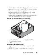
Disconnect the chassis intrusion switch cable from the INTRUSION
connector on the system board (see Figure 3-30).
5
Slide the chassis intrusion switch out of the securing bracket notch, then
remove the switch and its attached cable from the system.
Figure 3-30.
Removing and Installing the Chassis Intrusion Switch
Installing the Chassis Intrusion Switch
1
Align the chassis intrusion switch with the securing bracket notch (see
Figure 3-30).
2
Slide the switch into the securing bracket notch (see Figure 3-30).
1
securing bracket notch
2
chassis intrusion switch
3
INTRUSION connector on system
board
2
1
3
Summary of Contents for POWEREDGE T300
Page 10: ...10 Contents ...
Page 132: ...132 Installing System Components ...
Page 174: ...174 Jumpers and Connectors ...
Page 176: ...176 Getting Help ...
Page 188: ...188 Glossary ...

