1. Inspect the
system status LEDs
for an indication of component malfunction.
2. Turn off the system, including any attached peripherals.
3. If the system is connected to a power distribution unit (PDU), turn the PDU off and then on again.
If the system is not receiving power, plug the PDU into another electrical outlet. If it still is not receiving power, try
another PDU, and then reconnect the system to the electrical outlet or PDU.
4. Inspect the exterior of the system, including all controls and indicators, and all user-accessible data storage devices
for any signs of physical damage.
Does the inspection reveal any problems?
Yes
. Proceed to the appropriate procedure in "
Removing and Replacing Parts
."
No
. Proceed to "
Observing the Boot Routine
."
Observing the Boot Routine
NOTE:
To observe the boot routine, you must use the console redirection function on the serial port (COM1). See
the
System Administrator's Guide
for more information about console redirection.
Looking at and listening to the system are important in determining the source of a problem. Look and listen during the
system's startup routine for the indication described in Table 1.
Table 1. Startup Routine Indications
Look and Listen for:
Action
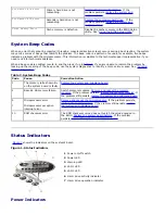
An error message (through console redirection) See "
Codes, Error Messages, and Indicators
."
The hard drive activity indicators
See "
Codes, Error Messages, and Indicators
."
A series of beeps
See "
Codes, Error Messages, and Indicators
."
An unfamiliar constant scraping or grinding
sound when you access a hard drive
See "
Hard Drives
" in "
Removing and Replacing Parts
."
Internal Visual Inspection
NOTICE:
Before you proceed with the internal visual inspection described in this section, ensure that the user has
saved all open files and exited all open application programs, if possible, to prevent loss of data.
A simple visual inspection of a system’s interior hardware can often lead to the source of a problem, such as a loose
expansion card, cable connector, or mounting screw. When you perform the visual inspection, see "
System Features
" to
locate components referenced in the inspection procedure.
To perform the internal visual inspection, perform the following steps:
1. Turn off the system, including any attached peripherals, and disconnect all the power cables from electrical outlets.
CAUTION:
Before beginning to work inside the system, disconnect the power supply from the power
source and the power supply cables from the power supply.
2. Remove the system cover as described in "
System Cover
."
CAUTION:
The microprocessor and heat-sink assembly can get extremely hot during system operations.
Be sure that it has had sufficient time to cool before touching it.
CAUTION:
When handling the microprocessor and heat-sink assembly, take care to avoid sharp edges
on the heat sink.
3. Verify that the memory modules, expansion cards, and microprocessor and heat-sink assembly or assemblies are
fully seated in their sockets or connectors.
4. To remove and reseat a microprocessor and heat-sink assembly, perform the steps described in "
Microprocessor
."
5. To remove and reseat a memory module, perform the steps described in "
Memory Modules
."
Summary of Contents for PowerVault 715N
Page 10: ...Back to Contents Page ...


