Ra c k I n s t a l l a t i o n G u i d e
1-15
5
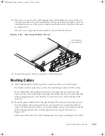
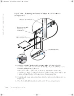
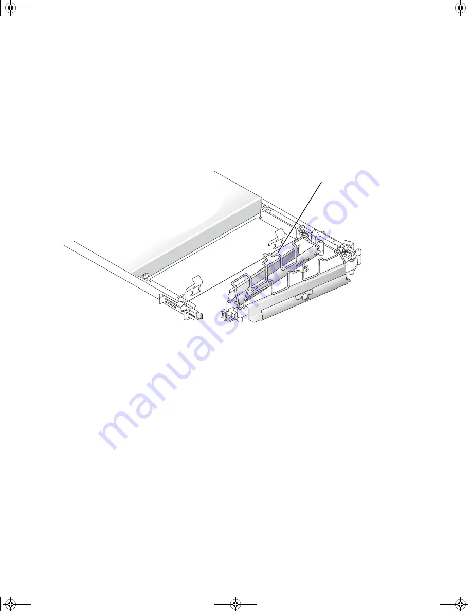
Open the wire covers on the cable-management arm by lifting the center of the wire
over the top of the embossed round button on the front of the forward part of the arm,
and lifting the wire over the top of a similar round button on the back part of the arm
(see Figure 1-10).
The wire cover swings open to allow cables to be routed within the arm.
F i g u r e 1 - 1 0 .
O p e n i n g t h e W i r e C o v e r s
6
Connect the power cord to its receptacle on the back panel.
Routing Cables
1
Attach the I/O cables to their respective connectors on the system back panel.
For details on cable connections, see the documentation provided with the system.
If you installed the cable-management arm on the right side (as viewed from the
back), use the Velcro cable strap on the right side of the cable tray. If you installed the
cable-management arm on the left side, use the Velcro strap on the left side of the
cable tray.
2
Route the power and I/O cables through the right Velcro strap on the cable tray and
then through the cable-management arm, using four loosely secured releasable tie-
wraps (two at the forward entrance, two in the middle, and one on the back end of the
cable-management arm). Do not fully tighten the tie-wraps at this time (see
Figure 1-11).
Allow some cable slack in the cable-management arm to prevent damage to the cables.
wire covers in
open position
JO525bk0.book Page 15 Monday, January 27, 2003 12:29 PM
Summary of Contents for PowerVault 725N
Page 6: ...6 Contents JO525bk0 book Page 6 Monday January 27 2003 12 29 PM ...
Page 42: ...6 Sommaire JO525fbk0 book Page 6 Monday January 27 2003 12 55 PM ...
Page 82: ...6 Inhalt JO525bk0 book Page 6 Monday January 27 2003 1 11 PM ...
Page 122: ...6 目次 JO525jbk0 book Page 6 Monday January 27 2003 3 13 PM ...
Page 160: ...6 Contenido JO525sbk0 book Page 6 Monday January 27 2003 4 29 PM ...

