14
About Your System
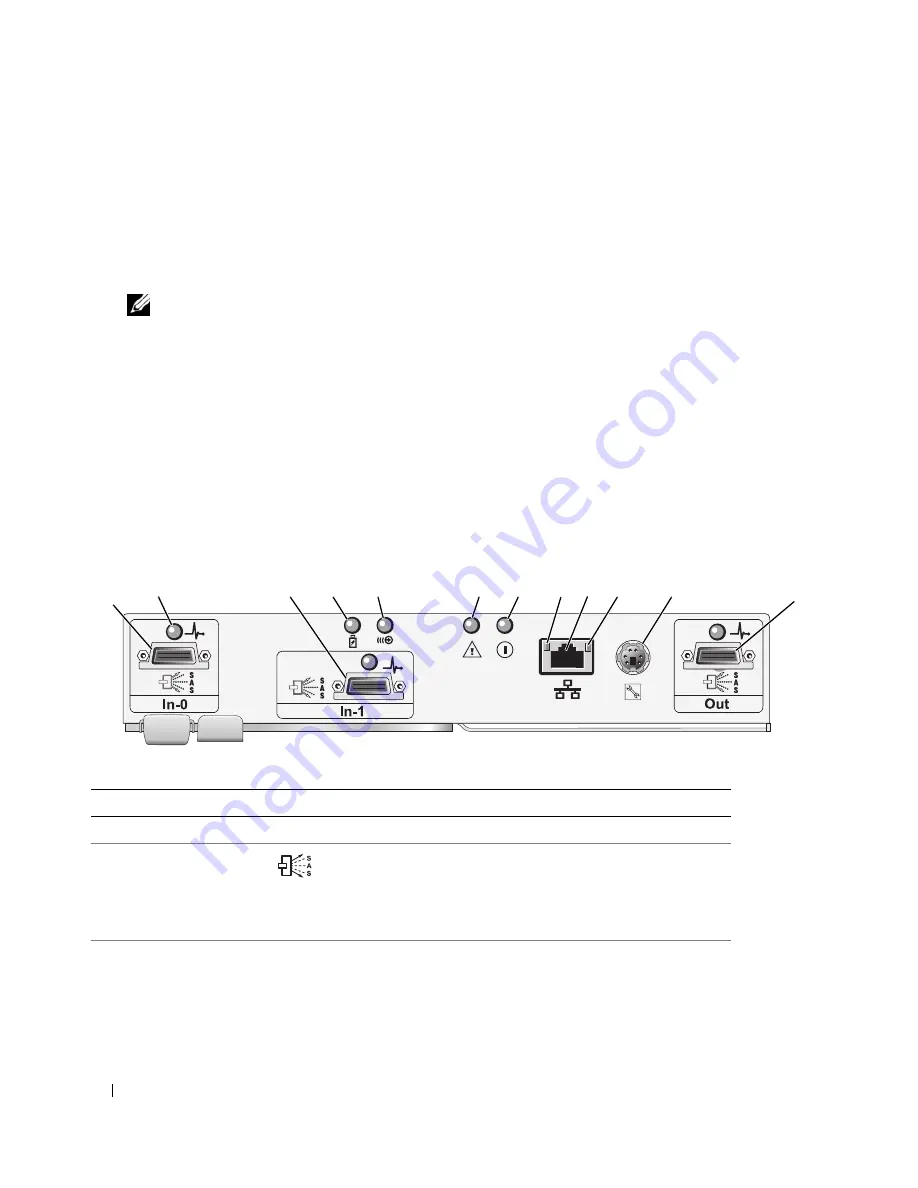
RAID Controller Module Connectors and Features
Figure 1-5 shows a single
RAID controller module
as it appears from the rear of the enclosure.
RAID
controller module
connectors and components shown include:
•
Up to two SAS In port connectors (second SAS In port is optional)
•
Ethernet connector
NOTE:
The RAID controller module network configuration can be assigned using a DHCP server (the default
setting). If a DHCP server is not available (time-out is 10 seconds) then the RAID controller modules uses the
static IP addresses of 192.168.128.101 for controller 0 and 192.168.128.102 for controller 1.
•
Nine LEDs (three SAS link, two Ethernet link/speed, Battery Fault, Cache Active, Controller Fault,
and Controller Power)
•
One SAS Out port connector (not used)
•
Debug port (Dell support only)
For a description of each component on the front panel of the RAID controller module, see Table 1-4.
For an explanation of how to connect the enclosure using the
RAID controller module
ports, see "Cabling
Your RAID Enclosure" on page 19.
Figure 1-5.
RAID Controller Module External Panel (front view)
Table 1-4.
RAID Controller Module Component Functions
Item Component
Icon
Function
1
SAS In Port 0
In-0
Provide host-to-controller SAS connection.
2
SAS LED
(each SAS port)
Green: All links in port connected.
Amber: Between one and four links disconnected.
Off: All links in port disconnected or cable
disconnected.
3
SAS In Port 1
(if available)
In-1
Provide host-to-controller SAS connection.
1
3
4
5
6
7
9
11
12
8
10
2
Summary of Contents for PowerVault MD3000
Page 68: ...68 Troubleshooting Your Enclosure ...
Page 100: ...100 Glossary ...


