6
Troubleshooting Your Computer
You can troubleshoot your computer using indicators like Diagnostic Lights, Beep Codes, and Error Messages during the
operation of the computer.
Diagnostic LEDs
NOTE: The diagnostic LEDs only serve as an indicator of the progress through the Power-On Self Test (POST)
process. These LEDs do not indicate the problem that caused the POST routine to stop.
The diagnostic LEDs are located on the front of the chassis next to the power button. These diagnostic LEDs are only
active and visible during the POST process. Once the operating system starts to load, they turn off and are no longer
visible.
Each LED has two possible states of OFF or ON. The most significant bit is labeled with the number 1, and the other three
are labeled 2, 3, and 4, as you go down or across the LED stack. The normal operating condition after POST is for all four
LEDs to be ON and then turn off as the BIOS hands control over to the operating system.
NOTE: The diagnostic lights will blink when the power button is amber or off, and will not blink when it is white.
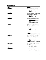
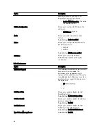
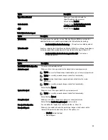
Table 11. POST Diagnostic LED Patterns
Diagnostic LEDs
•
The computer is either turned
off or is not receiving power
•
The computer is booted and
operating normally.
•
If the computer is turned off ,
connect the AC power-supply
and power-on the computer.
PCI device configuration activity is in
progress or PCI device failure was
detected.
•
Remove all peripheral cards
from the PCI and PCI-E slots
and reboot the computer. If
the computer boots, add the
peripheral cards back one by
one until you find the bad one.
A possible processor failure has
occurred.
•
Re-seat the processor.
Memory modules are detected, but a
memory power failure has occurred.
•
If two or more memory
modules are installed, remove
the modules, then reinstall
one module and re-start the
computer. If the computer
starts normally, continue to
install additional memory
modules (one at a time) until
you have identified a faulty
module or reinstalled all
modules without error. If only
one memory module is
63
Summary of Contents for Precision Workstation T7600
Page 1: ...Dell Precision Workstation T7600 Owner s Manual Regulatory Model D02X Regulatory Type D02X001 ...
Page 6: ...6 ...
Page 47: ...35 Internal USB 2 0 connector 36 HDD1 fan connector 37 Coin cell battery 47 ...
Page 48: ...48 ...
Page 62: ...62 ...
Page 68: ...68 ...
Page 76: ...76 ...

