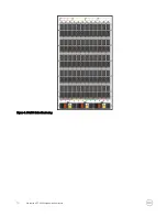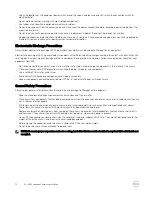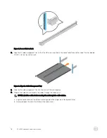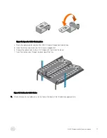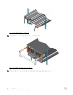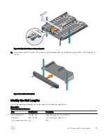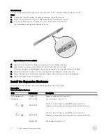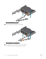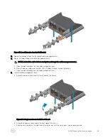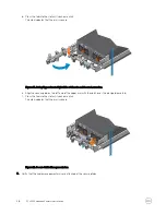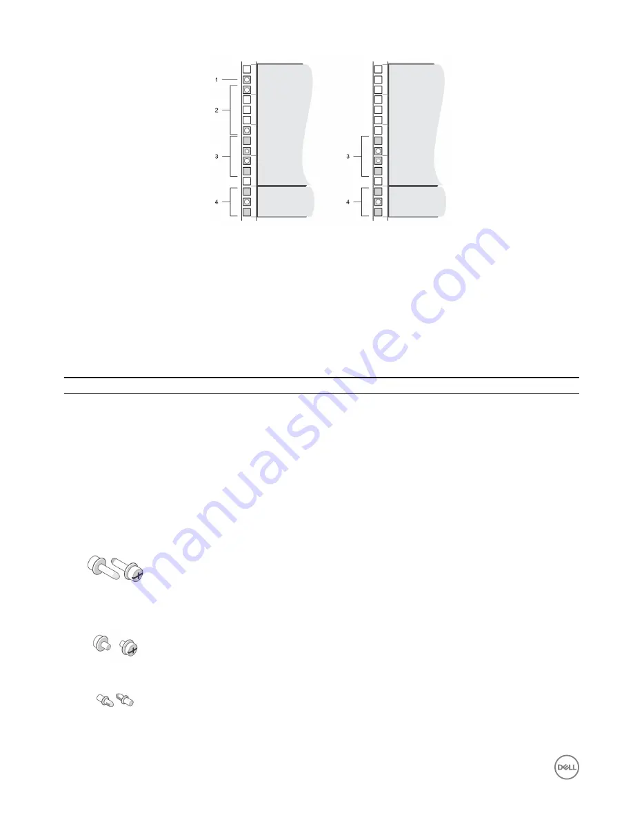
Figure 6. Mounting Location from Front and Back of Rack
1.
Location for the clip nuts to secure the top cover
2.
Location for the clip nuts to secure the expansion
enclosure
3.
Location for the expansion enclosure rack rails
4.
Location for the 1U cable management tray rails
Install the Cable Management Tray
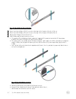
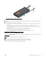
If you plan to use the 1U cable management tray, install the tray before installing the SCv360 expansion enclosure.
Prerequisite
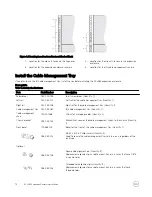
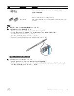
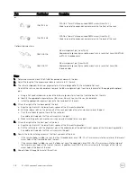
Table 1. Identify the Hardware
Part
Part Number
Description
Screwdriver
034-000-193
6-in-1 screwdriver (Quantity: 1)
Left rail
042-034-012
Left rail for the cable management tray (Quantity: 1)
Right rail
042-034-008
Right rail for the cable management tray (Quantity: 1)
Cable management tray 042-033-060
1U cable management tray (Quantity: 1)
Cable management
chain
150-000-168
Chains for managing cables (Quantity: 2)
Chassis bracket
043-043-023
Bracket that secures the cable management chains to the chassis (Quantity:
1)
Front bezel
100-563-123
Bezel for the front of the cable management tray (Quantity: 1)
036-034-012
#8-32 x 3/4 in. Phillips screw (Quantity: 5)
Used to secure the cable management tray rails to a rack, regardless of the
rack type
Optional
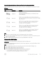
036-034-003
Square hole alignment pin (Quantity: 9)
Replacement alignment pin used to mount tray rails in racks that have 0.375
in. square holes
036-034-004
Threaded hole alignment pin (Quantity: 9)
Replacement alignment pin used to mount tray rails in racks that have
threaded holes
14
SCv360 Expansion Enclosure Installation


