background image

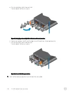
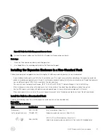
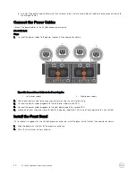
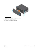
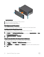
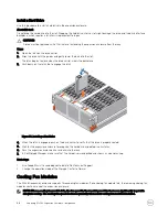
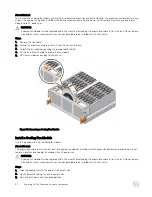
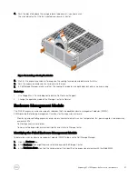
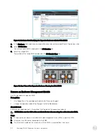
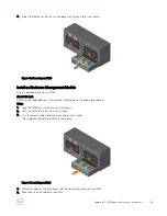
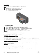
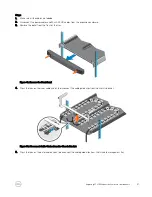
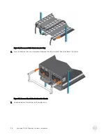
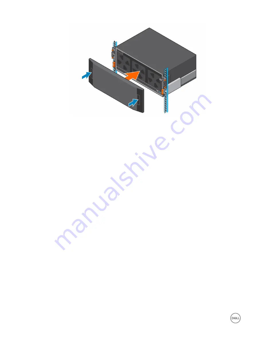
Figure 31. Install the Bezel

3.

Push the bezel into place until it attaches to the expansion enclosure.

4.

Release the latches on the front on the bezel.

5.

If the bezel has key lock, lock the bezel with the key.

Pre-Replacement Procedures

Perform the procedures described in this chapter before replacing a component of the SCv360 expansion enclosure.

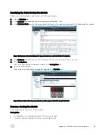
Send Diagnostic Data Using Dell SupportAssist

Before replacing components, use Dell SupportAssist to send diagnostic data to Dell Technical Support.

1.

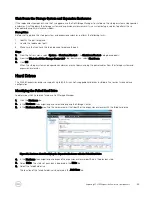
Use Dell Storage Manager to connect to the Storage Center.

2.

In the 

Summary

 tab, click 

Send SupportAssist Information Now

, which is located under 

SupportAssist Actions

 in the 

Status 

pane.
The 

Send SupportAssist Information Now

 dialog box opens.

3.

Select 

Storage Center Configuration

 and 

Detailed Logs

.

4.

Click 

OK

.

Change the Operation Mode of the Storage Center to Maintenance

Change the operation mode of the Storage Center to Maintenance before replacing components.

1.

Use Dell Storage Manager to connect to the Storage Center.

2.

In the 

Summary

 tab, click 

Edit Settings

. The 

Edit Storage Center Settings

 dialog box opens.

3.

Click the 

General

 tab.

4.

In the 

Operation Mode

 field select 

Maintenance

. Selecting 

Maintenance

 isolates alerts from those that would occur during 

normal operation.

5.

Click 

OK

.

34

Replacing SCv360 Expansion Enclosure Components

Summary of Contents for SCv360

Page 1: ...Dell SCv360 Expansion Enclosure Owner s Manual Regulatory Model CYAE ...

Page 2: ...e to hardware or loss of data and tells you how to avoid the problem WARNING A WARNING indicates a potential for property damage personal injury or death Copyright 2017 Dell Inc or its subsidiaries All rights reserved Dell EMC and other trademarks are trademarks of Dell Inc or its subsidiaries Other trademarks may be trademarks of their respective owners 2017 11 Rev B ...

Page 3: ... 13 Determine the Mounting Location 13 Install the Cable Management Tray 14 Modify the Rail Lengths 19 Install the Expansion Enclosure 20 Install the Cable Management Arms 23 Installing the Expansion Enclosure in a Non Standard Rack 27 Install the Rails in a Nonstandard Rack 27 Secure the Expansion Enclosure Chassis and Top Cover in a Nonstandard Rack 29 Connect the SAS Cables 29 Connect the Power...

Page 4: ... 44 Remove a PSU 45 Install a PSU 46 1U Cable Management Tray 46 Remove the Cable Management Tray 46 Install the Cable Management Tray 50 Cable Management Arms 54 Remove the Cable Management Arms 55 Install the Cable Management Arms 57 Expansion Enclosure Rack Rails 61 Remove the Expansion Enclosure Rails 61 Install the Expansion Enclosure Rails 62 Post Replacement Procedures 63 Start Up the Stora...

Page 5: ...ure such as installation instructions and technical specifications Dell Storage Center Release Notes Provides information about new features and known and resolved issues for the Storage Center software Dell Storage Center Update Utility Administrator s Guide Describes how to use the Storage Center Update Utility to install Storage Center software updates Updating Storage Center software using the...

Page 6: ...ctions for using the Data Collector Manager and the Dell Storage Manager Client Dell TechCenter Provides technical white papers best practice guides and frequently asked questions about Dell Storage products Go to http en community dell com techcenter storage 6 ...

Page 7: ...tures and Indicators The SCv360 front panel shows the expansion enclosure status and power supply status Figure 1 SCv360 Front Panel Features and Indicators Item Name Description 1 Power LED The power LED lights when at least one power supply unit is supplying power to the expansion enclosure 2 Expansion enclosure status LED The expansion enclosure status LED indicates when the system is being ide...

Page 8: ... supply is not connected to AC power or has a fault condition Flashing Green AC power is applied but is out of spec Power supply cooling fan indicator Amber Power supply cooling fan fault is detected Off Normal operation 3 Power supply unit and cooling fan module PS2 Contains redundant 900 W power supplies and fans that provide cooling for the expansion enclosure 4 Enclosure management module 1 EM...

Page 9: ...c off 1 sec Drive identification is enabled Steady amber Drive has a fault SCv360 Expansion Enclosure Drive Numbering The Storage Center identifies drives as XX YY where XX is the unit ID of the expansion enclosure that contains the drive and YY is the drive position inside the expansion enclosure An SCv360 holds up to 60 drives which are numbered from left to right in rows starting from 0 About t...

Page 10: ...Figure 4 SCv360 Drive Numbering 10 About the SCv360 Expansion Enclosure ...

Page 11: ...res in a rack fill the rack from the bottom up and empty the rack from the top down The rack construction must support the total weight of the installed expansion enclosures The design should incorporate stabilizing features suitable to prevent the rack from tipping or being pushed over during installation or in normal use To prevent the rack from tipping slide only one expansion enclosure out of ...

Page 12: ... modules and components Use a suitable ESD wrist or ankle strap Avoid contact with backplane components and module connectors Keep all components and printed circuit boards PCBs in their antistatic bags until ready for use General Safety Precautions Always follow general safety precautions to avoid injury and damage to Storage Center equipment Keep the area around the expansion enclosure chassis c...

Page 13: ...termine where to mount the SCv360 expansion enclosure in the rack 1 Identify a location in the rack with 4U of space for the expansion enclosure WARNING If you plan to install the expansion enclosure above the lower 20U of a rack use a mechanical lift to avoid injury 2 If you plan to install the 1U cable management tray below the expansion enclosure identify a location in the rack with 5U of space...

Page 14: ...ght rail for the cable management tray Quantity 1 Cable management tray 042 033 060 1U cable management tray Quantity 1 Cable management chain 150 000 168 Chains for managing cables Quantity 2 Chassis bracket 043 043 023 Bracket that secures the cable management chains to the chassis Quantity 1 Front bezel 100 563 123 Bezel for the front of the cable management tray Quantity 1 036 034 012 8 32 x 3...

Page 15: ...iate square hole or threaded hole alignment pins a Using a flat head screwdriver remove the alignment pins from the front and back of the rails b Identify the appropriate alignment pins square hole or threaded hole to use in the nonstandard rack c Install the appropriate alignment pins onto front and back of the rails 3 Align the rails so that the UP arrow is pointed in the correct direction and t...

Page 16: ...ent Tray 7 Slide the 1U cable management tray into the rails until it locks into place 8 Prepare the cable chains and route the cables through the cable chains NOTE Label the cables before routing them through the cable chains a Align the cable chains so the latches are facing up and the hinges are all facing each other b Unclip and open the all of the latches on the cable chains 16 SCv360 Expansi...

Page 17: ...ake sure that they are snapped shut e Arrange the cable chains to form a U shape with the latches facing up f Insert the cable chains through the back side of the tray Figure 11 Position the Cable Chains 9 Attach the clips on the cable chains to the tabs on the back of the 1U cable management rails SCv360 Expansion Enclosure Installation 17 ...

Page 18: ...the chassis bracket into the brackets on the side of the chassis Figure 13 Install the Chassis Bracket to the Chassis 11 Attach the clips on free end of the cable chains to the center flange on the chassis bracket 18 SCv360 Expansion Enclosure Installation ...

Page 19: ...nstall the Front Bezel Modify the Rail Lengths Use this procedure to extended or shorten the lengths of the expansion enclosure rails Prerequisite Table 2 Identify the Hardware Part Part Number Description Left and right rails 100 569 001 Expansion enclosure rails Quantity 2 Screwdriver 034 000 193 6 in 1 screwdriver Quantity 1 10 mm socket or wrench N A N A SCv360 Expansion Enclosure Installation...

Page 20: ...to free it 6 Adjust the hardware to make sure that the mounting holes are aligned with the mounting slots 7 Secure the length adjustment bracket in place using both screws and nuts that were removed earlier 8 Repeat the previous steps for the other rail Install the Expansion Enclosure Install the rails in the rack and mount the SCv360 expansion enclosure on the rails Prerequisite Table 3 Identify ...

Page 21: ...elease latch on the outer part of the rack post place the catch mechanism over the post c Push the rail back to secure the rail to the rack post An audible click indicates that the rail is secure in the post d Make sure the post catch mechanism is secure and attached to the rack post Figure 17 Attach Rail to the Back of the Rack 3 Attach the right rail to the front post of the rack a Align the rig...

Page 22: ...chanical lift using the chassis handles b If a mechanical lift is not available remove the drives cooling fans power supply units PSUs and enclosure management modules EMMs from the expansion enclosure chassis and lift the chassis to the mounting location using the chassis handles c From the front of the rack extend the rails approximately 5 to 8 cm 2 to 3 in and align the expansion enclosure chas...

Page 23: ...e expansion enclosure chassis to the rack using the orange shoulder screws d If the top cover is secured by two small shipping screws remove the screws e Secure the top cover of the expansion enclosure chassis to the rack using the shoulder screws Install the Cable Management Arms Installation of the cable management arms must be performed during a scheduled maintenance window when the Storage Cen...

Page 24: ...to alignment with the rail bracket Figure 22 Align Extension Arm with Rail Bracket 4 Push the extension arm into the rail bracket until you hear an audible click The audible click indicates that the cable management arm is secure 24 SCv360 Expansion Enclosure Installation ...

Page 25: ... arm b Route the power cables and the Mini SAS HD cables through the plastic brackets c Close the plastic brackets on the cable management arm 7 Close the cable management arms a Swing the lower arm back and to the left side of the chassis Figure 24 Swing Lower Arm to Left Side of Chassis b Swing the upper arm back and to the right side of the chassis c Align the securing tab on the right end of t...

Page 26: ...ower Arm e Align the securing tab on the left end of the upper arm with the notch over the orange release tab f Press the tab into the slot until you hear a click The click indicates that the arm is secure Figure 26 Secure Cable Management Arm 8 Verify that the cable management arms are attached at the securing tabs 26 SCv360 Expansion Enclosure Installation ...

Page 27: ...rails have four adjustment ranges 18 22 22 26 26 30 30 34 The default length is the 22 26 setting After installing a rail check the rail to make sure that it is level and in the correct location before installing the next rail Use the M5 screws which align with both round and square holes to secure all rails and components in the rack When securing rails to a rack install the screws loosely to pre...

Page 28: ...pins onto front and back of the rails 4 Attach the right rail to the back post of the rack a Align the right rail with the lower two U spaces of the 4U mounting location b With the release latch on the outer part of the rack post place the catch mechanism over the post c Push the rail back to secure the rail to the rack post An audible click indicates that the rail is secure in the post d Make sur...

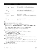
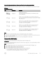
Page 29: ...expansion enclosure chassis and top cover to a nonstandard rack with 12 24 threaded holes Steps 1 Remove the semi captive M5 shoulder screws from the expansion enclosure chassis and top cover 2 In a rack with without threaded holes place M5 clip nuts into the mounting holes on the rack that line up with the holes on the expansion enclosure and top cover 3 Secure the expansion enclosure and top cov...

Page 30: ...ach power cable to the expansion enclosure using the strain relief clamp 3 Connect the power cables plugged into the left power supply to one PDU 4 Connect the power cables plugged into the right power supply to a second PDU 5 Label both ends of the power cords to identify the power supply and PDU to which each power cord is connected Install the Front Bezel If a front bezel is shipped with the SC...

Page 31: ...ezel 3 Push the bezel into place until it attaches to the expansion enclosure 4 Release the latches on the front on the bezel 5 If the bezel has key lock lock the bezel with the key SCv360 Expansion Enclosure Installation 31 ...

Page 32: ...he expansion enclosure chassis without using a mechanical lift if you remove the drives cooling fans power supply units PSUs and enclosure management modules EMMs from the chassis before installing it You must use a mechanical lift to install the expansion enclosure chassis if you do not remove the drives cooling fans PSUs and EMMs from the chassis Dell recommends that only individuals with rack m...

Page 33: ...zel with the key 2 Press the two latches on the front on the bezel 3 Pull the bezel away from the expansion enclosure Figure 30 Remove the Bezel Install the Front Bezel If a front bezel is shipped with the SCv360 expansion enclosure install the bezel on the front of the expansion enclosure 1 Align the bezel with the front of the expansion enclosure 2 Press the two latches on front of bezel Replaci...

Page 34: ...ary tab click Send SupportAssist Information Now which is located under SupportAssist Actions in the Status pane The Send SupportAssist Information Now dialog box opens 3 Select Storage Center Configuration and Detailed Logs 4 Click OK Change the Operation Mode of the Storage Center to Maintenance Change the operation mode of the Storage Center to Maintenance before replacing components 1 Use Dell...

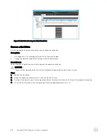
Page 35: ...nd expansion enclosures are shut down unplug the power cables from the storage system and expansion enclosures Hard Drives The SCv360 expansion enclosure supports up to 60 3 5 inch hot swappable hard drives installed in five row by twelve column configuration Identifying the Failed Hard Drive To determine which hard drive failed use Dell Storage Manager 1 Click the Hardware tab 2 In the Hardware t...

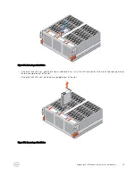
Page 36: ...a hard drive without shutting down the expansion enclosure CAUTION A drive must be replaced within 10 minutes of extending the expansion enclosure from the rack Steps 1 Remove the front bezel 2 Extend the expansion enclosure chassis from the front of the rack 3 To release the hard drive push the orange release tab on the drive carrier towards the front of the expansion enclosure 4 Lift the latch o...

Page 37: ...e up an additional 5 cm 2 in Wait 30 seconds for the drive to stop spinning and pull the drive completely out of the slot If the drive fault LED is off pull the drive completely out of the slot Figure 35 Removing a Hard Drive Replacing SCv360 Expansion Enclosure Components 37 ...
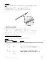
Page 38: ... the drive carrier to verify that the drive is properly seated 5 Wait for the expansion enclosure to recognize the hard drive and determine its status 6 Push the expansion enclosure chassis back into the rack 7 In Dell Storage Manager make sure that the hard drive is recognized and shown as up and running Next steps 1 Use SupportAssist to send diagnostic data to Dell Technical Support 2 Change the...

Page 39: ...b navigation pane expand the expansion enclosure identified in the previous step 5 Select Cooling Fans The status of each cooling fan module is displayed in the Cooling Fans tab 6 Select the failed cooling fan The location of the failed cooling fan module is displayed in the Fan View tab Figure 38 Rear View of the Expansion Enclosure Showing the Failed Cooling Fan Module Remove a Cooling Fan Modul...

Page 40: ...he left 4 Pull up on the latch handle to release the fan module 5 Pull the fan module up and out of the chassis Figure 39 Removing a Cooling Fan Module Install a Cooling Fan Module Use this procedure to install a cooling fan module About this task The expansion enclosure must have at least two cooling fan modules installed while the expansion enclosure is powered up Do not remove more than one coo...

Page 41: ...e SCv360 expansion enclosure supports redundant hot swappable enclosure management modules EMMs EMMs provide the following management functions for the expansion enclosure Monitoring and controlling expansion enclosure environment elements such as temperature fan power supplies and expansion enclosure LEDs Controlling access to hard drives Communicating expansion enclosure attributes and states to...

Page 42: ...nt Module Use this procedure to replace a EMM Prerequisites 1 Use SupportAssist to send diagnostic data to Dell Technical Support 2 Change the operation mode of the Storage Center to Maintenance About this task EMMs can be replaced one at a time without shutting down the expansion enclosure NOTE Make sure the SAS cables are labeled before disconnecting the cables from the EMM Steps 1 If the expans...

Page 43: ...ting down the expansion enclosure Steps 1 Align the EMM with the empty slot in the chassis 2 Push the EMM into the chassis until it stops 3 Turn the screw handle clockwise until a single click is heard The single click indicates the EMM is fully seated Figure 44 Installing an EMM 4 Match the labels on the SAS cables with the correct connectors on the EMM 5 Reconnect the SAS cables to the EMM Repla...

Page 44: ...ne which power supply unit PSU failed use the Dell Storage Manager 1 Click the Hardware tab 2 In the Hardware tab navigation pane select and expand the Storage Center 3 In the Hardware Alerts area find the hardware alert that identifies the expansion enclosure with the failed power supply Figure 45 Hardware Alert Identifying the Expansion Enclosure with the Failed Power Supply 4 In the Hardware ta...

Page 45: ...PSU without shutting down the expansion enclosure NOTE Make sure the power cables are labeled before disconnecting them from the PSU Steps 1 If the expansion enclosure is installed with cable management arms CMAs open the CMAs 2 Remove the strain relief clamps from the power cables and disconnect the power cables from the PSU 3 Turn the screw handle counter clockwise until the PSU is unseated from...

Page 46: ...Assist to send diagnostic data to Dell Technical Support 2 Change the operation mode of the Storage Center to Normal 1U Cable Management Tray The SCv360 expansion enclosure supports a 1U cable management tray If you plan to use the 1U cable management tray install the tray before installing the expansion enclosure The 1U cable management tray is installed in the 1U space below the expansion enclos...

Page 47: ...he tray Figure 49 Remove the Front Bezel 4 Press the tabs on the inner cable chains to disconnect the cable guide clips from the chassis bracket Figure 50 Disconnect Cable Chains from the Chassis Bracket 5 Press the tabs on the outer cable chains to disconnect the cable guide clips from the 1U cable management tray Replacing SCv360 Expansion Enclosure Components 47 ...
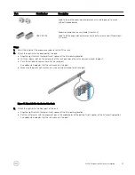
Page 48: ...ress the tabs on the chassis bracket and remove the chassis bracket from the sides of the chassis Figure 52 Remove Chassis Bracket from the Chassis 7 Unclip and open all the latches on the cable chains 48 Replacing SCv360 Expansion Enclosure Components ...
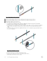
Page 49: ...e the tray Figure 54 Release Tray Using the Spring Clips 10 Pull the 1U cable management tray towards the front of the rack until it is free from the rails Figure 55 Remove Tray from the Rails 11 Remove the 8 32 x 0 75 in screws from the front and back of the rails 12 Pull back on the rails until the adaptors clear the front of the rack holes 13 Remove the rails from the rack Replacing SCv360 Expa...

Page 50: ... rails before installing the 1U cable management tray Figure 57 Push in Blue Tab on Expansion Enclosure Rails 2 Align the rails so that the UP arrow is pointed in the correct direction and the end of the rail labeled FRONT is at the front of the rack 3 Insert the alignment pins of left and right rails into the mounting holes at the front and back of the rack 4 Secure the rails by installing 8 32 x...

Page 51: ... into the Rails 6 Slide the tray into the rails until it locks into place 7 Prepare the cable chains and route the cables through the cable chains NOTE Label the cables before routing them through the cable chains a Align the cable chains so the latches are facing up and the hinges are all facing each other b Unclip and open all the latches on the cable chains Replacing SCv360 Expansion Enclosure ...

Page 52: ... sure that they are snapped shut e Arrange the cable chains to form a U shape with the latches facing up f Insert the cable chains through the back side of the tray Figure 61 Position the Cable Chains 8 Attach the clips on the cable chains to the tabs on the back of the 1U cable management tray 52 Replacing SCv360 Expansion Enclosure Components ...
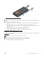
Page 53: ...ssis bracket into the brackets on the side of the chassis Figure 63 Install the Chassis Bracket to the Chassis 10 Attach the clips on free end of the cable chains to the center flange on the chassis bracket Replacing SCv360 Expansion Enclosure Components 53 ...
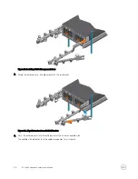
Page 54: ...ansion enclosure Next steps 1 Power on the expansion enclosure and storage system 2 Change the operation mode of the Storage Center to Normal 3 Use SupportAssist to send diagnostic data to Dell Technical Support Cable Management Arms The SCv360 expansion enclosure supports cable management arms in racks with a depth of 1200 mm 47 2 in The cable management arms attach to the back of the expansion e...

Page 55: ...Storage Center to Maintenance 3 Use Dell Storage Manager to shut down the storage system connected to the expansion enclosure Steps 1 Make sure all the cables are labeled 2 Disconnect the power cables and the Mini SAS HD cables from the expansion enclosure 3 Open the cable management arms a Press down on the orange release tab on the right side of the chassis Figure 66 Press Orange Release Tab b P...

Page 56: ...emove the power cables and the Mini SAS HD cables from the cable management arms a Open the plastic brackets on the cable management arm b Remove the cables from the plastic brackets c Close the plastic brackets on the cable management arm 5 Remove the lower cable management arm a Press down on the blue release tab and disconnect the extension arm from the rail bracket 56 Replacing SCv360 Expansio...

Page 57: ... disconnect the extension arm from the rail bracket b Press the tab on the cable management arm and disconnect the arm from the bracket Install the Cable Management Arms Installation of the cable management arms must be performed during a scheduled maintenance window when the Storage Center system is unavailable to the network About this task Install the cable management arms into a rack with a de...

Page 58: ...click indicates that the cable management arm is secure Figure 71 Installing Cable Management Arms 3 Swing the extension arm into alignment with the rail bracket Figure 72 Align Extension Arm with Rail Bracket 4 Push the extension arm into the rail bracket until you hear an audible click The audible click indicates that the cable management arm is secure 58 Replacing SCv360 Expansion Enclosure Com...

Page 59: ... b Route the power cables and the Mini SAS HD cables through the plastic brackets c Close the plastic brackets on the cable management arm 7 Close the cable management arms a Swing the lower arm back and to the left side of the chassis Figure 74 Swing Lower Arm to Left Side of Chassis b Swing the upper arm back and to the right side of the chassis c Align the securing tab on the right end of the l...

Page 60: ... Arm e Align the securing tab on the left end of the upper arm with the notch over the orange release tab f Press the tab into the slot until you hear a click The click indicates that the arm is secure Figure 76 Secure Cable Management Arm 8 Verify that the cable management arms are attached at the securing tabs 60 Replacing SCv360 Expansion Enclosure Components ...
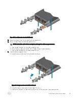
Page 61: ...ystem is unavailable to the network Prerequisites 1 Use SupportAssist to send diagnostic data to Dell Technical Support 2 Change the operation mode of the Storage Center to Maintenance 3 Use Dell Storage Manager to shut down the storage system connected to the expansion enclosure Steps 1 Make sure all the cables are labeled 2 Disconnect the power cables and Mini SAS HD cables from the expansion en...

Page 62: ...d attached to the rack post Figure 78 Attach Rail to the Back of the Rack 3 Attach the right rail to the front post of the rack a Align the right rail with the lower two U spaces of the 4U mounting location b Pull the rail forward with the alignment pins in the middle holes of the bottom two U spaces of the 4U mounting location An audible click indicates that the rail is secure in the post Figure ...

Page 63: ...orage system 3 Power on the storage system by pressing the power switches on both power supply cooling fan modules to the ON position 4 Use the Dell Storage Manager to make sure the replacement part is recognized and shown as up and running Send Diagnostic Data Using Dell SupportAssist After replacing components use Dell SupportAssist to send diagnostic data to Dell Technical Support 1 Use Dell St...
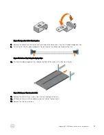
Page 64: ...S ports per EMM The expansion enclosure supports Mini SAS HD cables in lengths of 3 m 4 m and 5 m SAS connectors SAS connectors are SFF 8644 compliant AC Power Power supply wattage 1600 W per power supply AC line voltage 200 to 240 VAC 10 single phase 47 to 63 Hz AC line current operating maximum 4 9 A max at 200 Vac Power consumption operating maximum 980 VA 931 W max Power factor 0 95 min at ful...

Page 65: ...ture gradation of 10 C per hour Storage 40 to 65 C 40 to 149 F with a maximum temperature gradation of 25 C per hour Relative humidity Operating 20 to 80 noncondensing Storage 10 to 90 noncondensing Altitude Operating 16 to 2300 m 50 to 7500 ft Storage 16 to 10 600 m 50 to 35 000 ft SCv360 Expansion Enclosure Technical Specifications 65 ...

Reviews: