background image

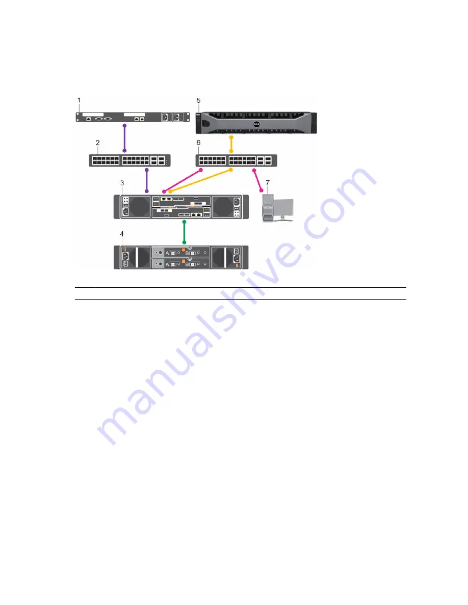
SCv2000/SCv2020 Storage System with Fibre Channel Front-End Connectivity

An SCv2000/SCv2020 storage system with Fibre Channel front-end connectivity may communicate with 
the following components of a Storage Center system.

Figure 3. Storage System with Fibre Channel Front-End Connectivity

Item Description

Speed

Communication Type

1

Server with Fibre Channel host bus adapters 

(HBAs)

8 Gbps or 16 Gbps

Front End

2

Fibre Channel switch

8 Gbps or 16 Gbps

Front End

3

SCv2000/SCv2020 storage system with FC 

front-end connectivity

8 Gbps or 16 Gbps

Front End

4

SC100/SC120 expansion enclosures

6 Gbps per channel

Back End

5

Remote Storage Center connected via iSCSI 

for replication

1 Gbps or 10 Gbps

Front End

6

Ethernet switch

1 Gbps or 10 Gbps 

(Management/
Replication)

Front End

7

Management network (computer connected 

to the storage system through the Ethernet 
switch)

Up to 1 Gbps

System Administration

12

About the SCv2000/SCv2020 Storage System

Summary of Contents for Storage Center SCv2000

Page 1: ...Dell Storage Center SCv2000 and SCv2020 Storage System Deployment Guide ...
Page 2: ...problem WARNING A WARNING indicates a potential for property damage personal injury or death Copyright 2015 Dell Inc All rights reserved This product is protected by U S and international copyright and intellectual property laws Dell and the Dell logo are trademarks of Dell Inc in the United States and or other jurisdictions All other marks and names mentioned herein may be trademarks of their res...

Page 3: ...Cv2020 Storage Controller Features and Indicators 17 SCv2000 SCv2020 Drives 23 SCv2000 SCv2020 Storage System Drive Numbering 23 SC100 SC120 Expansion Enclosure Overview 24 SC100 SC120 Expansion Enclosure Front Panel Features and Indicators 24 SC100 SC120 Expansion Enclosure Back Panel Features and Indicators 25 SC100 SC120 Expansion Enclosure EMM Features and Indicators 26 SC100 SC120 Expansion E...
Page 4: ...bling the Management Port and Replication Port for iSCSI Replication 65 Cabling the Embedded Ports for iSCSI Host Connectivity 66 Two iSCSI Networks using the Embedded Ethernet Ports on a Storage System with Dual Fibre Channel Storage Controllers 66 Two iSCSI Networks Using the Embedded Ethernet Ports on a Storage System with Dual iSCSI Storage Controllers 68 4 Back End Cabling and Connecting Powe...

Page 5: ...rtAssist 85 Provide Contact Information 85 Update Storage Center 85 Complete Configuration and Perform Next Steps 86 Set Up a localhost or VMware Host 86 Set Up a localhost from Initial Setup 86 Set Up a VMware vSphere Host from Initial Setup 87 Set Up a VMware vCenter Host from Initial Setup 87 Configure Embedded iSCSI Ports 88 6 Perform Post Setup Tasks 89 Verify Connectivity and Failover 89 Cre...

Page 6: ...Expansion Enclosure to the B Side of the Chain 100 Label the Back End Cables 102 Removing an Expansion Enclosure from a Chain Currently in Service 103 Release the Disks in the Expansion Enclosure 103 Disconnect the SC100 SC120 Expansion Enclosure from the A Side of the Chain 104 Disconnect the SC100 SC120 Expansion Enclosure from the B Side of the Chain 105 B Troubleshooting Storage Center Deploym...

Page 7: ...support browse the product list on the support page and select your product Related Publications The following documentation is available for the SCv2000 SCv2020 storage system Dell Storage Center SCv2000 and SCv2020 Storage System Getting Started Guide Provides information about an SCv2000 SCv2020 storage system such as installation instructions and technical specifications Dell Storage Center SC...
Page 8: ... Center Command Utility The Command Utility provides a command line interface CLI to enable management of Storage Center functionality on Windows Linux Solaris and AIX platforms Dell Storage Center Command Set for Windows PowerShell Provides instructions for getting started with Windows PowerShell cmdlets and scripting objects that interact with the Storage Center using the PowerShell interactive ...

Page 9: ...e SCv2000 and SCv2020 are 2U storage systems with built in storage The SCv2000 is a 2U storage system that supports up to 12 internal 3 5 inch hot swappable SAS hard drives installed in a four column three row configuration The SCv2020 is a 2U storage system that supports up to 24 internal 2 5 inch hot swappable SAS hard drives installed vertically side by side The SCv2000 SCv2020 storage system c...

Page 10: ...sures as long as the total disk count of the system does not exceed 168 Storage Center Architecture Options A Storage Center with an SCv2000 SCv2020 storage system can be deployed in the following configurations An SCv2000 SCv2020 storage system deployed without SC100 SC120 expansion enclosures Figure 1 SCv2000 SCv2020 without Expansion Enclosures An SCv2000 SCv2020 storage system deployed with on...

Page 11: ...rage by connecting to the storage system Fibre Channel ports through one or more Fibre Channel switches Connecting host servers directly to the storage system without using Fibre Channel switches is not supported When replication is licensed the SCv2000 SCv2020 can use the front end Fibre Channel ports to replicate data to another Storage Center iSCSI Hosts servers or Network Attached Storage NAS ...

Page 12: ...apters HBAs 8 Gbps or 16 Gbps Front End 2 Fibre Channel switch 8 Gbps or 16 Gbps Front End 3 SCv2000 SCv2020 storage system with FC front end connectivity 8 Gbps or 16 Gbps Front End 4 SC100 SC120 expansion enclosures 6 Gbps per channel Back End 5 Remote Storage Center connected via iSCSI for replication 1 Gbps or 10 Gbps Front End 6 Ethernet switch 1 Gbps or 10 Gbps Management Replication Front E...

Page 13: ...SCSI ports or iSCSI host bus adapters HBAs 1 Gbps or 10 Gbps Front End 2 Ethernet switch 1 Gbps or 10 Gbps Front End 3 SCv2000 SCv2020 storage system with iSCSI front end connectivity 1 Gbps or 10 Gbps Front End 4 SC100 SC120 expansion enclosures 6 Gbps per channel Back End 5 Remote Storage Center connected via iSCSI for replication 1 Gbps or 10 Gbps Front End 6 Management network computer connect...

Page 14: ... system with SAS front end connectivity 12 Gbps per channel Front End 4 SC100 SC120 expansion enclosures 6 Gbps per channel Back End 5 Remote Storage Center connected via iSCSI for replication 1 Gbps or 10 Gbps Front End 6 Management network computer connected to the storage system through the Ethernet switch Up to 1 Gbps System Administration Back End Connectivity Back end connectivity is strictl...

Page 15: ...rollers Each storage controller contains the front end back end and management communication ports of the storage system SCv2000 SCv2020 Storage System Front Panel Features and Indicators The front panel of the SCv2000 SCv2020 contains power and status indicators a system identification button and a unit ID display In addition the hard drives are installed and removed through the front of the stor...
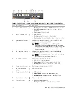
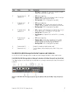
Page 16: ...ains the storage controller indicators and power supply indicators Figure 7 SCv2000 SCv2020 Back Panel View Item Name Icon Description 1 Power supply cooling fan module PSU 2 Contains a 580 W power supply and fans that provide cooling for the storage system 2 Battery backup unit BBU 2 Allows the storage controller to shut down smoothly when a loss of AC power is detected 3 Storage controller 1 or ...

Page 17: ...nd the PSU is in standby mode 7 DC power fault indicator 2 Off Normal operation Steady amber PSU has been removed a DC or other hardware fault has occurred or the storage system is having a problem communicating with the PSU Blinking amber PSU is in programming mode 8 Power socket 2 Accepts a standard computer power cord 9 Power switch 2 Controls power for the storage system Each PSU has one switc...

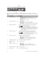
Page 18: ...red To use the MGMT port as a front end connection to host servers a Flex Port license is required 4 REPL port Slot 3 Port 2 Ethernet iSCSI port that is typically used for replication to another Storage Center requires a replication license NOTE To use the RELP port as a front end connection to host servers a Flex Port license is required 5 SAS activity indicators There are four SAS PHYs per SAS p...

Page 19: ...1 and Slot 1 Port 2 with three LEDs per port Fibre Channel ports All off No power All on Booting up Blinking amber 2 Gbps activity Blinking green 4 Gbps activity Blinking yellow 8 Gbps activity Blinking amber and yellow Beacon All blinking simultaneous Firmware initialized All blinking alternating Firmware fault 15 Mini SAS port B Slot 2 Port 2 Back end expansion port B 16 Mini SAS port A Slot 2 P...

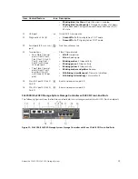
Page 20: ...e MGMT port as a front end connection to host servers a Flex Port license is required 4 REPL port Slot 3 Port 2 Ethernet iSCSI port that is typically used for replication to another Storage Center NOTE To use the RELP port as a front end connection to host servers a Flex Port license is required 5 SAS activity indicators There are four SAS PHYs per SAS port Off SAS PHY is not connected Steady gree...

Page 21: ... Mini SAS port B Slot 2 Port 2 Back end expansion port B 16 Mini SAS port A Slot 2 Port 1 Back end expansion port A SCv2000 SCv2020 Storage System Storage Controller with SAS Front End Ports The following figure shows the features and indicators on a storage controller with SAS front end ports Figure 12 SCv2000 SCv2020 Storage System Storage Controller with Four 12 Gb SAS Front End Ports Item Cont...
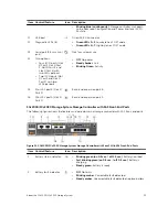
Page 22: ...ler completed POST 7 Recessed power off button Not currently used 8 Storage controller module fault Off No faults Steady amber Firmware has detected an error Blinking amber Storage controller is performing POST 9 Recessed reset button Not currently used 10 Identification LED Off Identification disabled Blinking blue for 15 sec Identification is enabled Blinking blue continuously Storage controller...

Page 23: ...detected and has no faults 2 Drive status indicator Off Normal operation Blinking amber on 1 sec off 1 sec Drive identification is enabled Blinking amber on 2 sec off 1 sec Hardware firmware fault Steady amber Drive is safe to remove SCv2000 SCv2020 Storage System Drive Numbering In an SCv2000 SCv2020 storage system the drives are numbered from left to right Dell Storage Client identifies drives a...
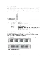
Page 24: ...gure 16 SC100 Front Panel Features and Indicators Figure 17 SC120 Front Panel Features and Indicators Item Name Icon Description 1 Expansion enclosure status indicator Lights when the expansion enclosure power is on Off No power On steady blue Normal operation Blinking blue Storage Center is identifying the enclosure On steady amber Expansion enclosure is turning on or was reset Blinking amber Exp...

Page 25: ... power or has a fault condition 2 Power supply cooling fan indicator Amber Power supply cooling fan fault is detected Off Normal operation 3 AC power indicator Green Power supply module is connected to a source of AC power whether or not the power switch is on Off Power supply module is disconnected from a source of AC power 4 Power socket 2 Accepts a standard computer power cord 5 Power switch 2 ...

Page 26: ...losure is not connected 5 SAS port B out Connects to a storage controller or to other SC100 SC120 expansion enclosures SAS ports A and B can be used for either input or output However for cabling consistency use port B as an output port 6 Port B link status Green All the links to the port are connected Amber One or more links are not connected Off Expansion enclosure is not connected 7 EMM status ...

Page 27: ... Drive is detected and there are no faults 2 Drive status indicator Steady green Normal operation Blinking green on 1 sec off 1 sec Drive identification is enabled Steady amber Drive is safe to remove Off No power to the drive SC100 SC120 Expansion Enclosure Drive Numbering In an SC100 SC120 expansion enclosure the drives are numbered from left to right starting from 0 Dell Storage Client identifi...

Page 28: ...ugh space to accommodate the storage system chassis expansion enclosures and switches Power Power must be available in the rack and the power delivery system must meet the requirements of the Storage Center Connectivity The rack must be wired for connectivity to the management network and any networks that carry front end IO from the Storage Center to servers Safety Precautions Always follow these...

Page 29: ...er from the storage system when removing or installing components that are not hot swappable When disconnecting power first power down the storage system using the Dell Storage Client and then unplug the power cords from all the power supplies in the storage system Provide a suitable power source with electrical overload protection All Storage Center components must be grounded before applying pow...

Page 30: ...sis do not wear loose clothing such as neckties and unbuttoned shirt sleeves which can come into contact with electrical circuits or be pulled into a cooling fan Remove any jewelry or metal objects from your body because they are excellent metal conductors that can create short circuits and harm you if they come into contact with printed circuit boards or areas where power is present Do not lift a...

Page 31: ...e front of the rack and one at the back Figure 24 Hole Locations in Rack 1 Pin hole 2 Rack mounting screw hole 3 Pin hole 4 Insert a screw into the rack mounting screw hole at the front of the rack and tighten the screw to secure the rail to the rack Figure 25 Insert the Screw into the Rack Mounting Screw Hole 5 Extend the rail to fit the rack and insert the two rail pins into the pin holes at the...

Page 32: ...ail 8 Slide the storage system chassis onto the rails Figure 27 Mount the SCv2000 SCv2020 Storage System Chassis 9 Secure the storage system chassis to the rack using the mounting screws within each chassis ear a Lift the latch on each chassis ear to access the screws b Tighten the screws to secure the chassis to the rack c Close the latch on each chassis ear 32 Install the Storage Center Hardware...

Page 33: ...o the Rack 10 If the Storage Center system includes expansion enclosures mount the expansion enclosures in the rack See the instructions included with the expansion enclosure for detailed steps Install the Storage Center Hardware 33 ...

Page 34: ...ler become active Multipath IO MPIO When multiple paths are available from a server to a storage system a server configured for multipath IO can use multiple paths for IO If a path becomes unavailable the server continues to use the remaining available paths Port redundancy If a single port becomes unavailable the port can move to another available port in the same fault domain Storage controller ...

Page 35: ...rts on the same storage controller MPIO Configuration Instructions for Host Servers To use MPIO configure MPIO on the host server If a Dell Storage Client wizard is used to configure host server access to the Storage Center the Dell Storage Client attempts to automatically configure MPIO with best practices NOTE Compare the host server settings applied by the Dell Storage Client wizard against the...

Page 36: ...nd make sure that the HBAs have the latest supported firmware 3 Use the Fibre Channel cabling diagrams to cable the host servers to the switches Connecting host servers directly to the storage system without using Fibre Channel switches is not supported Two Fibre Channel Fabrics with Dual 16 Gb 2 Port Storage Controllers Use two Fibre Channel FC fabrics to prevent an unavailable port switch or sto...

Page 37: ...Fibre Channel Fabrics with Dual 8 Gb 4 Port Storage Controllers Use two Fibre Channel FC fabrics to prevent an unavailable port switch or storage controller from causing a loss of connectivity between host servers and a storage system with dual 8 Gb 4 port storage controllers About this task This configuration includes two fault domains two FC fabrics and two FC switches The storage controllers co...

Page 38: ...Storage controller 2 port 4 to FC switch 2 Example Figure 30 Storage System with Dual 8 Gb Storage Controllers and Two FC Switches 1 Server 1 2 Server 2 3 FC switch 1 fault domain 1 4 FC switch 2 fault domain 2 5 Storage system 6 Storage controller 1 7 Storage controller 2 Next steps Install or enable MPIO on the host servers NOTE After the Storage Center configuration is complete run the host acc...
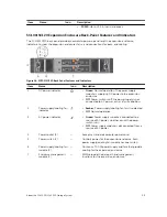
Page 39: ...troller move to physical ports on the other storage controller NOTE This configuration is vulnerable to switch unavailability which results in a loss of connectivity between the host servers and storage system Steps 1 Connect each server to the FC fabric 2 Connect fault domain 1 shown in orange to the fabric Storage controller 1 port 1 to the FC switch Storage controller 2 port 1 to the FC switch ...

Page 40: ...ecomes unavailable the virtual port moves to another physical port in the same fault domain on the same storage controller If a storage controller becomes unavailable the virtual ports on the offline storage controller move to the physical ports on the other storage controller NOTE This configuration is vulnerable to switch unavailability which results in a loss of connectivity between the host se...

Page 41: ...Controller Use two Fibre Channel FC fabrics to prevent an unavailable port or switch from causing a loss of connectivity between the host servers and a storage system with a single 16 Gb 2 port storage controller About this task This configuration includes two fault domains two FC fabrics and two FC switches The storage controller connects to each FC switch using one FC connection If a physical po...

Page 42: ...re Channel FC fabrics to prevent an unavailable port or switch from causing a loss of connectivity between the host servers and a storage system with a single 8 Gb 4 port storage controller About this task This configuration includes two fault domains two FC fabrics and two FC switches The storage controller connects to each FC switch using two FC connections If a physical port becomes unavailable...

Page 43: ...all or enable MPIO on the host servers NOTE After the Storage Center configuration is complete run the host access wizard to configure host server access and apply MPIO best practices For the latest best practices see the Dell Storage Center Best Practices document on the Dell TechCenter site http en community dell com techcenter storage Using SFP Transceiver Modules An SCv2000 SCv2020 storage sys...

Page 44: ...ge the transceiver module or the port The SFP transceiver module must be installed into a port before you connect the fiber optic cable The fiber optic cable must be removed from the SFP transceiver module before you remove the transceiver module from the port Install an SFP Transceiver Module Complete the following steps to install an SFP transceiver module in a 16 Gb FC storage controller About ...

Page 45: ...s 5 Insert the other end of the fiber optic cable into the SFP transceiver module of a Fibre Channel switch Remove an SFP Transceiver Module Complete the following steps to remove an SFP transceiver module from a 16 Gb FC storage controller Prerequisites Use failover testing to make sure that the connection between host servers and the Storage Center remains up if the port is disconnected About th...

Page 46: ...zones must be established to ensure that storage is visible to the servers Use the zoning concepts discussed in this section to plan the front end connectivity before starting to cable the storage system Zoning can be applied to either the ports on switches or to the World Wide Names WWNs of the end devices Dell recommends creating zones using a single initiator host port and multiple Storage Cent...

Page 47: ... single server HBA port and all Storage Center ports Create server zones that contain all Storage Center front end ports and a single server port For Fibre Channel replication include all Storage Center front end ports from Storage Center system A and Storage Center system B in a single zone Labeling the Front End Cables Label the front end cables to indicate the storage controller and port to whi...

Page 48: ...pter have the latest supported firmware c Use the host operating system to assign IP addresses for each iSCSI port The IP addresses must match the subnets for each fault domain CAUTION Correctly assign IP addresses to the HBAs or network adapters Assigning IP addresses to the wrong ports can cause connectivity issues NOTE If using jumbo frames they must be enabled and configured on all devices in ...

Page 49: ... switch or storage controller from causing a loss of connectivity between the host servers and a storage system with dual 10 GbE 2 port storage controllers About this task This configuration includes two fault domains two iSCSI networks and two Ethernet switches The storage controllers connect to each Ethernet switch using one iSCSI connection If a physical port or Ethernet switch becomes unavaila...

Page 50: ...unavailable port switch or storage controller from causing a loss of connectivity between the host servers and a storage system with dual 1 GbE 4 port storage controllers About this task This configuration includes two fault domains two iSCSI networks and two Ethernet switches The storage controllers connect to each Ethernet switch using two iSCSI connections If a physical port becomes unavailable...

Page 51: ...controller 1 7 Storage controller 2 Next steps Install or enable MPIO on the host servers NOTE After the Storage Center configuration is complete run the host access wizard to configure host server access and apply MPIO best practices For the latest best practices see the Dell Storage Center Best Practices document on the Dell TechCenter site http en community dell com techcenter storage One iSCSI...

Page 52: ...rt 1 to the Ethernet switch 3 Connect fault domain 2 shown in blue to the iSCSI network Storage controller 1 port 2 to the Ethernet switch Storage controller 2 port 2 to the Ethernet switch Example Figure 42 Storage System with Dual 10 GbE Storage Controllers and One Ethernet Switch 1 Server 1 2 Server 2 3 Ethernet switch fault domain 1 and fault domain 2 4 Storage system 5 Storage controller 1 6 ...

Page 53: ...orts on the offline storage controller move to the physical ports on the other storage controller NOTE This configuration is vulnerable to switch unavailability which results in a loss of connectivity between the host servers and the storage system Steps 1 Connect each server to the iSCSI network 2 Connect fault domain 1 shown in orange to the iSCSI network Storage controller 1 port 1 to the Ether...

Page 54: ... two iSCSI networks to prevent an unavailable port or switch from causing a loss of connectivity between the host servers and a storage system with a single 10 GbE 2 port storage controller About this task This configuration includes two fault domains two iSCSI networks and two Ethernet switches The storage controller connects to the Ethernet switches using two iSCSI connections If a physical port...

Page 55: ...works to prevent an unavailable port or switch from causing a loss of connectivity between the host servers and a storage system with a single 1 GbE 4 port storage controller About this task In this configuration there are two fault domains two iSCSI networks and two Ethernet switches The storage controller connects to each Ethernet switch using two iSCSI connections If a physical port becomes una...

Page 56: ... the host access wizard to configure host server access and apply MPIO best practices For the latest best practices see the Dell Storage Center Best Practices document on the Dell TechCenter site http en community dell com techcenter storage Labeling the Front End Cables Label the front end cables to indicate the storage controller and port to which they are connected Prerequisites Locate the pre ...

Page 57: ...ling Direct Attached Host Servers An SCv2000 SCv2020 storage system with SAS front end ports connects directly to host servers Preparing Host Servers On each host server install the SAS host bus adapters HBAs install the drivers and make sure that the latest supported firmware is installed About this task NOTE Refer to the Dell Storage Compatibility Matrix for a list of supported SAS HBAs Steps 1 ...

Page 58: ...th for those volumes is set to Active Optimized NOTE Failover in SAS virtual port mode occurs within a single fault domain Therefore a server must have both connections in the same fault domain For example if a server is connected to SAS port 2 on one storage controller it must be connected to SAS port two on the other storage controller If a server is not cabled correctly when a storage controlle...

Page 59: ...s For the latest best practices see the Dell Storage Center Best Practices document on the Dell TechCenter site http en community dell com techcenter storage Four Servers Connected to Dual 12 Gb 4 Port SAS Storage Controllers A storage system with four 12 Gb front end SAS ports on each storage controller can connect to up to four host servers if each host server has one HBA with dual SAS ports Abo...

Page 60: ...t 3 to host server 3 b Connect a SAS cable from storage controller 2 port 3 to host server 3 4 Connect fault domain 4 shown in red to host server 4 a Connect a SAS cable from storage controller 1 port 4 to host server 4 b Connect a SAS cable from storage controller 2 port 4 to host server 4 Example Figure 49 Storage System with Dual 12 Gb SAS Storage Controllers Connected to Four Host Servers 1 Se...
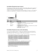
Page 61: ...OTE This configuration is vulnerable to storage controller unavailability which results in a loss of connectivity between the host servers and the storage system Steps 1 Connect fault domain 1 to host server 1 by connecting a SAS cable from storage controller 1 port 1 to host server 1 2 Connect fault domain 2 to host server 1 by connecting a SAS cable from storage controller 1 port 2 to host serve...

Page 62: ...rerequisites Locate the pre made front end cable labels that shipped with the storage system About this task Apply cable labels to both ends of each cable that connects a storage controller to a front end fabric or network or directly to host servers Steps 1 Starting with the top edge of the label attach the label to the cable near the connector Figure 51 Attach Label to Cable 2 Wrap the label aro...

Page 63: ...ller 1 5 Storage controller 2 NOTE If the Flex Port license is installed the management port becomes a shared iSCSI port To use the management port as an iSCSI port cable the management port to a network switch dedicated to iSCSI traffic Special considerations must be taken into account when sharing the management port The Flex Port feature allows both Storage Center system management traffic and ...

Page 64: ...to an Ethernet switch and used for iSCSI replication If the Storage Center is licensed for replication and the Flex Port license is installed the management port and replication port can both be connected to an Ethernet switch and used for iSCSI replication Cabling the Replication Port for iSCSI Replication If replication is licensed the replication REPL port can be used to replicate data to anoth...

Page 65: ...Replication If replication is licensed and the Flex Port license is installed the management MGMT port and replication REPL port can be used to replicate data to another Storage Center About this task Connect the management port and replication port on each storage controller to an Ethernet switch through which the Storage Center can perform replication NOTE The Flex Port feature allows both Stora...

Page 66: ... Storage Center the management port and replication port can be connected to an Ethernet switch and used for iSCSI host connectivity Dell recommends using two switches dedicated for iSCSI traffic Refer to the iSCSI Settings appendix for a list of recommend and required settings Two iSCSI Networks using the Embedded Ethernet Ports on a Storage System with Dual Fibre Channel Storage Controllers Use ...

Page 67: ...main 1 shown in orange to iSCSI network 1 a Connect the management port on storage controller 1 to Ethernet switch 1 b Connect the management port on storage controller 2 to Ethernet switch 1 4 Connect embedded fault domain 2 shown in blue to iSCSI network 2 a Connect the replication port on storage controller 1 to Ethernet switch 2 b Connect the replication port on storage controller 2 to Etherne...

Page 68: ...ches If a physical port or Ethernet switch becomes unavailable the storage system is accessed from the switch in the other fault domain If a storage controller becomes unavailable the virtual ports on the offline storage controller move to the physical ports on the other storage controller NOTE The Flex Port feature allows both Storage Center system management traffic and iSCSI traffic to use the ...

Page 69: ...SCSI Ports link on the Configuration Complete page of the Discover and Configure Uninitialized SCv2000 Series Storage Centers wizard Next steps Install or enable MPIO on the host servers NOTE After the Storage Center configuration is complete run the host access wizard to configure host server access and apply MPIO best practices For the latest best practices see the Dell Storage Center Best Pract...

Page 70: ...n a storage system and expansion enclosures is referred to as a SAS chain A SAS chain is made up of two paths which are referred to as the A side and B side Each side of the SAS chain starts at the initiator only SAS port on one storage controller and ends at the initiator target SAS port the other storage controller SAS Redundancy Use redundant SAS cabling to make sure that an unavailable IO port...

Page 71: ...ontroller 2 port A to the storage controller 1 port B Back End Connections for an SCv2000 SCv2020 with Expansion Enclosures The SCv2000 SCv2020 storage system supports a total of 168 disks per Storage Center system The SCv2000 supports up to thirteen SC100 expansion enclosures up to six SC120 expansion enclosures or any combination of SC100 SC120 expansion enclosures as long as the total disk coun...

Page 72: ...k end SAS connections from an SCv2000 SCv2020 to one SC100 SC120 expansion enclosure Table 4 SCv2000 SCv2020 Connected to One SC100 SC120 Expansion Enclosure Path Connections Chain 1 A Side Orange 1 Storage controller 1 port A to the expansion enclosure top EMM port A 2 Expansion enclosure top EMM port B to storage controller 2 port B Chain 1 B Side Blue 1 Storage controller 2 port A to the expans...

Page 73: ... expansion enclosures Table 5 SCv2000 SCv2020 Connected to Two SC100 SC120 Expansion Enclosures Path Connections Chain 1 A Side Orange 1 Storage controller 1 port A to expansion enclosure 1 top EMM port A 2 Expansion enclosure 1 top EMM port B to expansion enclosure 2 top EMM port A 3 Expansion enclosure 2 top EMM port B to storage controller 2 port B Chain 1 B Side Blue 1 Storage controller 2 por...

Page 74: ...ble labels to both ends of each SAS cable to indicate the chain number and side A or B Steps 1 Starting with the top edge of the label attach the label to the cable near the connector Figure 64 Attach Label to Cable 2 Wrap the label around the cable until it fully encircles the cable The bottom of each label is clear so that it does not obscure the text Figure 65 Wrap Label Around Cable 3 Apply a ...

Page 75: ...e connecting the power cables 2 Connect the power cables to both power supply cooling fan modules in the storage system chassis and secure the power cables firmly to the brackets using the straps provided Figure 66 Connect the Power Cables 3 Plug the other end of the power cables into a grounded electrical outlet or a separate power source such as an uninterrupted power supply UPS or a power distr...

Page 76: ... and press both power buttons again to turn on the storage system 5 Wait until the green diagnostic LEDs on the back of each storage controller match the pattern shown in the following figure This LED pattern indicates that a storage controller has started up successfully NOTE It could take up to 5 minutes for a storage controller to completely start up Figure 68 Storage Controller Diagnostic LEDs...

Page 77: ...st setup wizards The storage system hardware must be installed and cabled before the Storage Center can be configured Locating Your Service Tag Your storage system is identified by a unique Service Tag number You can find the Service Tag number on the service luggage tag located next to the front panel display The Service Tag number is also located on the back of the storage system chassis Dell us...

Page 78: ...er address ___ ___ ___ ___ Table 7 Storage Center Administrator Password for the default Storage Center Admin user ________________ Email address of the default Storage Center Admin user ________________ iSCSI Fault Domain Information For a storage system with iSCSI front end ports gather and record network information for the iSCSI fault domains This information is needed to complete the Discover...

Page 79: ...he Discover and Configure Uninitialized SCv2000 Series Storage Centers wizard Table 10 NTP SMTP and Proxy Servers NTP server IPv4 address ___ ___ ___ ___ SMTP server IPv4 address ___ ___ ___ ___ Backup SMTP server IPv4 address ___ ___ ___ ___ SMTP server login ID ________________ SMTP server password ________________ Proxy server IPv4 address ___ ___ ___ ___ Fibre Channel Zoning Information For a ...

Page 80: ..._______________ 4 port I O card only Virtual WWN of storage controller 2 port 4 ________________ Supported Operating Systems for Storage Center Automated Setup Setting up a Storage Center using the Discover and Configure Uninitialized SCv2000 Series Storage Center wizard and the Host Setup wizards requires 64 bit versions of the following operating systems Red Hat Enterprise Linux 6 or later SUSE ...

Page 81: ...ions Ensure that the Storage Center is physically attached to all necessary networks and powered on Then click Rediscover Click Troubleshoot Storage Center Hardware Issue to learn more about reasons why the Storage Center is not discoverable Click Manually Discover Storage Center via MAC Address to enter the MAC address for the Storage Center 3 Select the Storage Center to initialize 4 Optional Cl...

Page 82: ...ars Configure iSCSI Fault Domains For a Storage Center with iSCSI front end ports use the Configure iSCSI Fault Domains page and the Fault Domain pages to enter network information for the fault domains and ports 1 Optional On the Configure iSCSI Fault Domains page click More information about fault domains or How to set up an iSCSI network to learn more about these topics 2 Click Next NOTE If any...

Page 83: ...e not connected to the storage network and then click OK 2 When all of the Storage Center setup tasks are complete click Next Review Fibre Channel Front End Configuration For a Storage Center with Fibre Channel front end ports the Fault Domains page displays an example of a fault domain topology based on the number of controllers and type of front end ports The Review Front End Configuration page ...

Page 84: ...t to Use Authorized Login and then enter the ID and password 5 Click Next Configure Key Management Server Settings The Key Management Server Settings page appears if supported by the Storage Center license Use this page to enter network settings and select the certificate files 1 Enter network settings for the server 2 Enter the user name and password 3 Select the SSL certificate files 4 Click Nex...

Page 85: ...t emails select Yes I would like to receive emails from Dell SupportAssist when issues arise including hardware failure notifications 3 Select the preferred contact method language and available times 4 Enter a shipping address where replacement Storage Center components can be sent 5 Click Next Update Storage Center The Storage Center attempts to contact the SupportAssist Update Server to check f...

Page 86: ... Initial Setup Configure a localhost to access block level storage on the Storage Center Prerequisites Client must be running on a system with a 64 bit operating system The Dell Storage Client must be run by a Dell Storage Client user with the Administrator privilege On a Storage Center with Fibre Channel IO ports configure Fibre Channel zoning before starting this procedure Steps 1 On the Configu...

Page 87: ...l other cases the Verify vSpheres Information page appears Proceed to the next step 3 Select an available port and then click Create Server The server definition is created on the Storage Center 4 The Host Setup Successful page displays the best practices that were set by the wizard and best practices that were not set Make a note of any best practices that were not set by the wizard It is recomme...

Page 88: ...edded iSCSI Ports Configure the embedded Ethernet ports on the Storage Center for use as iSCSI ports 1 If the Flex Port license is installed configure the fault domain and ports for Flex Port Domain 1 NOTE The Flex Port feature allows both Storage Center system management traffic and iSCSI traffic to use the same physical network ports However for environments where the Storage Center system manag...

Page 89: ...ller storage controller 1 a Click the Storage tab b From the Storage tab navigation pane select the Volumes node c Click Create Volume The Create Volume wizard appears d Enter TestVol1 in the Name field then click Next e Set the volume size to 25 GB then click Next f Select the disk folder to use then click Next g Select the replay profile to use then click Next h Select the server to which to map...

Page 90: ...s d Wait several minutes and verify that the storage controller has finished restarting Test MPIO Perform the following tests for a Storage Center with Fibre Channel or iSCSI front end connectivity if the network environment and servers are configured for MPIO Always perform the following tests for a Storage Center with SAS front end connectivity 1 Create a Test folder on the server and copy at le...

Page 91: ...itate easy identification in the rack use the Dell Storage Client to match each expansion enclosure ID to a Service Tag Locate the Service Tag on the back of each expansion enclosure and then label it with the correct expansion enclosure ID NOTE If the expansion enclosure is deleted from the Storage Client and then added back in the expansion enclosure is assigned a new index number which requires...

Page 92: ...92 Perform Post Setup Tasks ...

Page 93: ...re The Add New Enclosure wizard starts a Click Next to validate the existing cabling b Select the enclosure type and click Next c If the drives are not installed install the drives in the expansion enclosures d Turn on the expansion enclosure When the drives spin up make sure that the front panel and power status LEDs show normal operation e Click Next f Add the expansion enclosure to the A side c...

Page 94: ...nt before Adding Expansion Enclosures Use the Dell Storage Client to determine the number of drives that are currently accessible to the Storage Center 1 Connect to the Storage Center using the Dell Storage Client 2 Select the Storage tab 3 In the Storage tab navigation pane select the Disks node 4 On the Disks tab record the number of drives that are accessible by the Storage Center Compare this ...

Page 95: ...he chain top EMM port B Figure 72 Connect the A Side Cables to the Expansion Enclosures 1 Storage system 2 Storage controller 1 3 Storage controller 2 4 Expansion enclosure 1 5 Expansion enclosure 2 Add the SC100 SC120 Expansion Enclosures to the B Side of the Chain Connect the expansion enclosures to one side of the chain at a time to maintain drive availability 1 Remove the B side cable shown in...

Page 96: ...n enclosure 1 5 Expansion enclosure 2 2 Cable the expansion enclosures to the B side of the chain a Connect a SAS cable from storage controller 1 port B to expansion enclosure 2 bottom EMM port B b Connect a SAS cable from storage controller 2 port A to expansion enclosure 1 bottom EMM port A 96 Adding or Removing an Expansion Enclosure ...

Page 97: ...t the storage controllers or label the back end cables that connect the storage system to the expansion enclosures Prerequisites Locate the cable labels provided with the expansion enclosures About this task Apply cable labels to both ends of each SAS cable to indicate the chain number and side A or B Steps 1 Starting with the top edge of the label attach the label to the cable near the connector ...

Page 98: ...ervice Use caution when adding an expansion enclosure to a live Storage Center system to preserve the integrity of the existing data Prerequisites Install the expansion enclosure in a rack but do not connect the expansion enclosure to the storage system For more information see the Dell Storage Center SC100 SC120 Expansion Enclosure Getting Started Guide About this task To add an expansion enclosu...

Page 99: ... more information see the Dell Enterprise Manager Administrator s Guide 6 Label the new back end cables Related Tasks Check the Current Disk Count before Adding Expansion Enclosures Add an SC100 SC120 Expansion Enclosure to the A Side of the Chain Add an SC100 SC120 Expansion Enclosure to the B Side of the Chain Label the Back End Cables Check the Disk Count before Adding an Expansion Enclosure Us...

Page 100: ... 2 top EMM port B Figure 78 Connect A Side Cables to the New Expansion Enclosure 1 Storage system 2 Storage controller 1 3 Storage controller 2 4 Expansion enclosure 1 5 New expansion enclosure 2 Add an SC100 SC120 Expansion Enclosure to the B Side of the Chain Connect the expansion enclosure to one side of the chain at a time to maintain drive availability 1 Disconnect the B side cable shown in b...

Page 101: ...e to connect expansion enclosure 1 bottom EMM port B to the new expansion enclosure 2 bottom EMM port A 3 Connect the B side cable that was disconnected in step 1 to the new expansion enclosure 2 bottom EMM port B Figure 80 Connect B Side Cables to the New Expansion Enclosure 1 Storage system 2 Storage controller 1 3 Storage controller 2 4 Expansion enclosure 1 Adding or Removing an Expansion Encl...

Page 102: ...ask Apply cable labels to both ends of each SAS cable to indicate the chain number and side A or B Steps 1 Starting with the top edge of the label attach the label to the cable near the connector Figure 81 Attach Label to Cable 2 Wrap the label around the cable until it fully encircles the cable The bottom of each label is clear so that it does not obscure the text Figure 82 Wrap Label Around Cabl...

Page 103: ...ick Next b Reconnect the A side cables to exclude the expansion enclosure from the chain Click Next to validate the cabling 7 Disconnect the B side chain a Disconnect the B side cables that connect the expansion enclosure to the storage system Click Next b Reconnect the B side cables to exclude the expansion enclosure from the chain Click Next to validate the cabling 8 Click Finish Related Tasks R...

Page 104: ...ct the A side cables from the expansion enclosure that you want to remove 1 Disconnect the A side cable shown in orange from expansion enclosure 1 top EMM port A The B side cables continue to carry IO while the A side is disconnected 2 Remove the A side cable between expansion enclosure 1 top EMM port B and expansion enclosure 2 top EMM port A Figure 83 Disconnecting the A Side Cables from the Exp...

Page 105: ... from the B Side of the Chain Disconnect the B side cables from the expansion enclosure that you want to remove 1 Disconnect the B side cable shown in blue from expansion enclosure 1 bottom EMM port A The A side cables continue to carry IO while the B side is disconnected 2 Remove the B side cable between expansion enclosure 1 bottom EMM port B and expansion enclosure 2 bottom EMM port A Adding or...

Page 106: ...losure 2 3 Connect the B side cable to expansion enclosure 2 bottom EMM port A The expansion enclosure is now disconnected and can be removed Figure 86 Reconnecting the B Side Cable to the Remaining SC100 SC120 Expansion Enclosure 1 Storage system 2 Storage controller 1 3 Storage controller 2 4 Disconnected expansion enclosure 106 Adding or Removing an Expansion Enclosure ...

Page 107: ...5 Expansion enclosure 1 Adding or Removing an Expansion Enclosure 107 ...

Page 108: ...108 Adding or Removing an Expansion Enclosure ...

Page 109: ...Recheck the link status indicators If the link status indicators are not green replace the cables Troubleshooting Hard Drives To troubleshoot hard drives 1 Check the status of the hard drive using the Dell Storage Client 2 Determine the status of the hard drive indicators If the hard drive status indicator blinks amber on 2 seconds off 1 second the hard drive has failed If the hard drive status in...

Page 110: ...lient 2 If an expansion enclosure and or drives are missing in the Dell Storage Client you may need to check for and install Storage Center updates to use the expansion enclosure and or drives 3 If an expansion enclosure firmware update fails check the back end cabling and ensure that redundant connections are used 110 Troubleshooting Storage Center Deployment ...

Reviews: