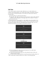

6. Trouble Shooting Instructions
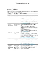
Product Specific Problems
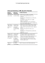
Problem
What You
Experience
Possible Solutions
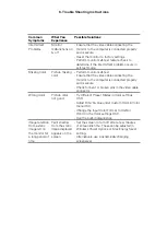
Screen image is
too small
Image is
centered on
screen, but
does not fill
entire viewing
area
• Check the Aspect Ratio setting in the Display
menu OSD.
• Reset the monitor to factory settings.
Cannot adjust
the monitor
with the
buttons on the
front panel
OSD does not
appear on the
screen
• Turn off the monitor, unplug the monitor power
cable, plug it back, and then turn on the monitor.
No Input Signal
when user
controls are
pressed
No picture, the
LED light is
white
• Check the signal source. Ensure the computer
is not in the power saving mode by moving the
mouse or pressing any key on the keyboard.
• Check whether the signal cable is plugged
in properly. Connect the signal cable again, if
necessary.
• Reset the computer or video player.
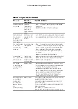
The picture
does not fill the
entire screen
The picture
cannot fill the
height or width
of the screen
• Due to different video formats (aspect ratio) of
DVDs, the monitor may display in full screen.
• Run the built-in diagnostics.
No image
when using DP
connection to
the PC
Black screen
• Verify which DP standard (DP 1.1a or DP 1.4) is
your Graphics Card certified to. Download and
install the latest graphics card driver.
• Some DP 1.1a graphics card cannot support
DP 1.4 monitors. Go to OSD menu, under Input
Source selection, press and hold DP select
Joystick key for 8 seconds to change the
monitor setting from DP 1.4 to DP 1.1a.
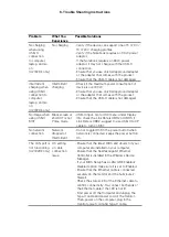
No image when
using USB-C
connection
to computer,
laptop, and so
on
(U2722DE only)
Black screen
• Verify if the USB-C interface of the device can
support DP alternate mode.
• Verify if the device required more than 90 W
power charging.
• USB-C interface of device cannot support DP
alternate mode.
• Set Windows to Projection mode.
• Ensure that the USB-C cable is not damaged.


