
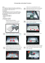
5. Disassembly and Assembly Procedures
S10
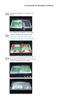
S9
S11
S12
S8
U
.
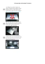
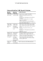
se a Philips-head screwdriver to remove 4pcs
screws for unlocking the bracket chassis module
with the panel
(No.1~4 Screw size= M3x5, Torque=5
±0.5
kgfxcm)
Move up the bracket, then push the earing-lock and
disconnect the LVDS cable away from the connectors
of the panel module.
Take away the bracket chassis module and then put
the bracket chassis module on a protective cushion.
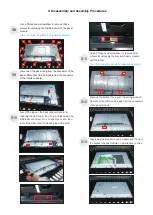
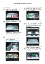
S13
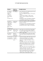
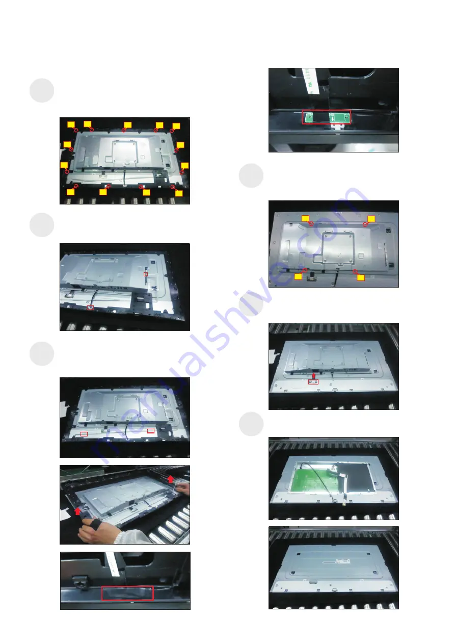
Use a Philips-head screwdriver to remove 13pcs
screws for unlocking the middle bezel with the panel
module.
(No.1~13 screw size=M3x5, Torque=5
±
0.5
kgfxcm)
Disconnect the panel lamp from the connector of the
panel. Disconnect the LED cable from the connector
of the interface board.
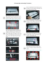
Tear off the tape on the back of panel module for
releasing the LED cable, then
middle bezel, and put it on a cushion foam, and then
tear off the mylar tape for releasing the LED board.
lift up and take away the
3
11
10
13
12
8
2
9
4
5
7
6
1
4
1
1
1


