Back to Contents Page
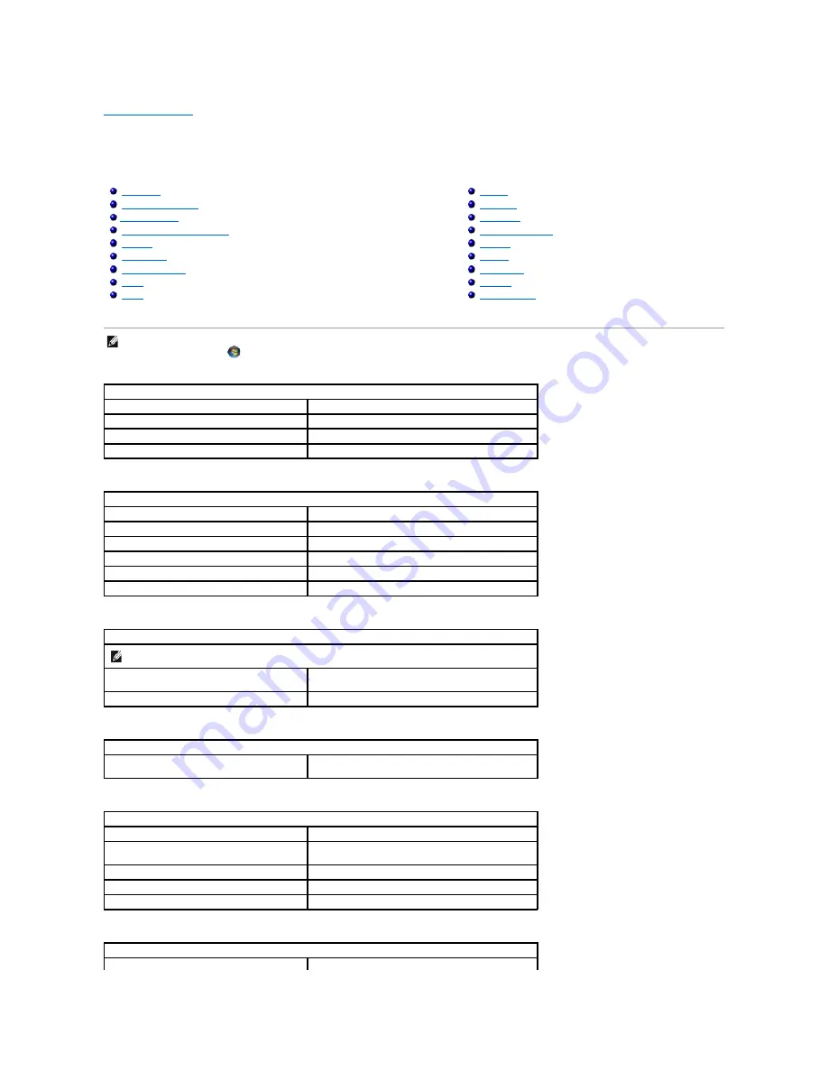
Specifications
Dell™ Vostro™ 1520 Service Manual
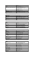
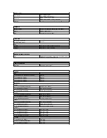
Processor
System Information
ExpressCard™
8-in-1 Memory Card Reader
Memory
Connectors
Communications
Video
Audio
Display
Keyboard
Touch Pad
Fingerprint Reader
Camera
Battery
AC Adapter
Physical
Environmental
NOTE:
Offerings may vary by region. For more information regarding the configuration of
your Tablet-PC, click
Start
(or
Start
in Windows XP)
®
Help and Support
, and then
select the option to view information about your Tablet-PC.
Processor
Processor type
Intel
® Core™ 2 Duo processors
L1 cache
32 KB per instruction, 32 KB data cache per core
L2 cache
Shared 3 MB or 6 MB
External bus frequency
1067 MHz
System Information
System chipset
Intel GM45 or Intel PM45 chipset
Data bus width
64 bits
DRAM bus width
64 bits
Processor address bus width
36 bits
Flash EPROM
SPI 32 Mbit
PCI bus (discrete graphics only)
x16 PCI Express
ExpressCard™ (optional)
NOTE:
The ExpressCard slot is designed only for ExpressCards. It does NOT support PC cards.
ExpressCard connector
ExpressCard slot (USB and PCI Express-based
interfaces)
Cards supported
34-mm and 54-mm ExpressCards
Secure Digital (SD) Memory Card Reader
Cards supported
SD, SDIO, SD HC, Mini SD (with adapter) MMC, MMC+,
Mini MMC (with adapter)
Memory
Memory module connector
Two DIMM sockets
Memory module capacities
1 GB (one DIMM), 2 GB (one DIMM or two DIMMs), 3 GB (2
DIMMs), 4 GB (2 DIMMs)
Memory type
DDR2 800 MHz non-ECC memory only.
Minimum memory
1024 MB (1 GB)
Maximum memory
4096 MB (4 GB)
Connectors
Audio
Microphone connector and stereo headphone/speakers
Summary of Contents for Vostro 1520
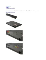
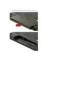
Page 12: ...4 Slide the battery itself toward the back of the computer and remove ...
Page 14: ......
Page 16: ...5 Remove the bezel from the display assembly ...
Page 19: ......
Page 22: ......
Page 25: ......
Page 27: ......
Page 31: ......
Page 33: ...6 Lift the fan and remove it from the computer ...
Page 36: ...15 Remove the fingerprint reader from the palm rest ...
Page 40: ......
Page 42: ...5 Remove the hard drive and mini card access panel ...
Page 45: ......
Page 47: ...5 Remove the memory module from the socket ...
Page 49: ...6 Remove the optical drive from the computer ...
Page 53: ......
Page 55: ...5 Remove the access panel ...
Page 58: ......
Page 60: ......
Page 63: ......
Page 66: ...15 Lift the inside edge of the USB board and remove the board from the computer ...
Page 67: ......
Page 69: ......
Page 72: ......
Page 74: ......


