Back to Contents Page
System Board
Dell™ Vostro™ 1520 Service Manual
Removing the System Board
1.
Follow the procedures in
Before Working Inside Your Computer
.
2.
Remove any ExpressCards and SD cards from the computer.
3.
Remove the
battery
from the computer.
4.
Remove the
processor and memory access panel
from the computer.
5.
Remove the
fan
from the computer.
6.
Remove the
heat sink and processor
from the computer.
7.
Remove the
memory
modules from the computer.
8.
Remove the
coin-cell battery
from the computer.
9.
Remove the
hard drive and mini-card access panel
from the computer.
10.
Remove the
hard drive
from the computer.
11.
Remove the
optical drive
from the computer.
12.
Remove the
Bluetooth module
from the computer.
13.
Remove any
WLAN
and
WWAN
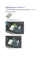
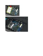
cards from the computer.
14.
Remove the
hinge cover
from the computer.
15.
Remove the
keyboard
from the computer.
16.
Remove the
display assembly
from the computer.
17.
Remove the
palm rest
from the computer.
18.
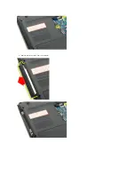
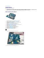
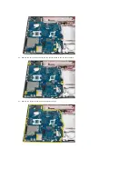
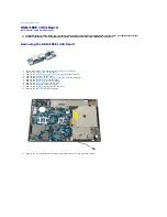
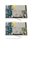
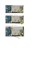
Disconnect the first data cable from the system board.
19.
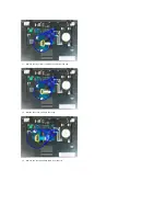
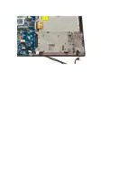
Disconnect the second data cable from the system board.
WARNING:
Before working inside your Tablet-PC, read the safety information that shipped with your Tablet-PC. For additional safety best
practices information, see the Regulatory Compliance Homepage at www.dell.com/regulatory_compliance.
Summary of Contents for Vostro 1520
Page 12: ...4 Slide the battery itself toward the back of the computer and remove ...
Page 14: ......
Page 16: ...5 Remove the bezel from the display assembly ...
Page 19: ......
Page 22: ......
Page 25: ......
Page 27: ......
Page 31: ......
Page 33: ...6 Lift the fan and remove it from the computer ...
Page 36: ...15 Remove the fingerprint reader from the palm rest ...
Page 40: ......
Page 42: ...5 Remove the hard drive and mini card access panel ...
Page 45: ......
Page 47: ...5 Remove the memory module from the socket ...
Page 49: ...6 Remove the optical drive from the computer ...
Page 53: ......
Page 55: ...5 Remove the access panel ...
Page 58: ......
Page 60: ......
Page 63: ......
Page 66: ...15 Lift the inside edge of the USB board and remove the board from the computer ...
Page 67: ......
Page 69: ......
Page 72: ......
Page 74: ......


