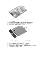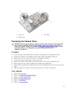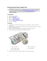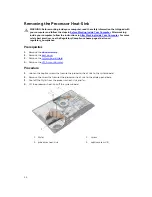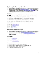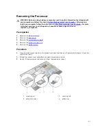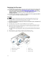
6.
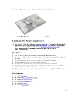
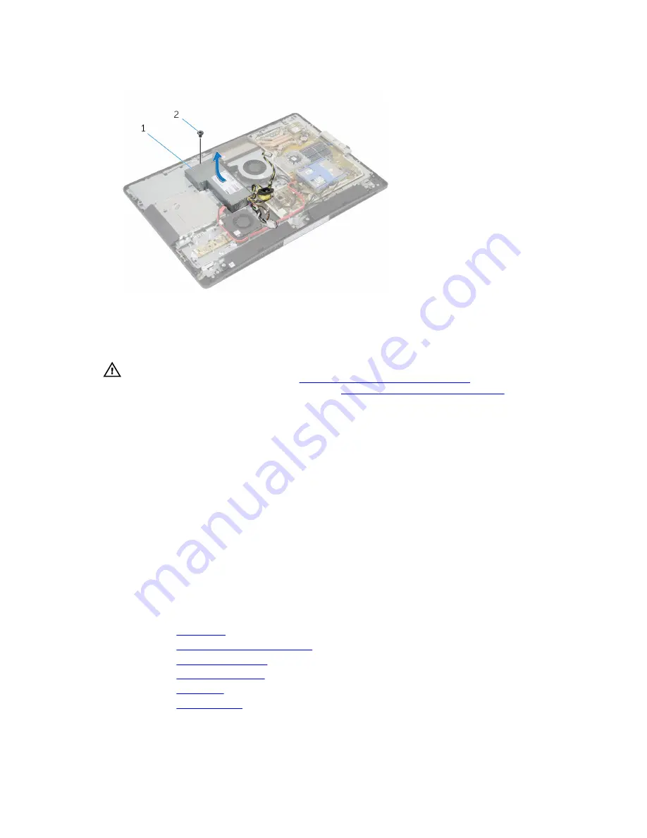
Slide and lift the power-supply unit to release it from the display-panel base.
1.
power-supply unit
2. screw
Replacing the Power-Supply Unit
WARNING: Before working inside your computer, read the safety information that shipped with
your computer and follow the steps in
Before Working Inside Your Computer
. After working
inside your computer, follow the instructions in
After Working Inside Your Computer
. For more
safety best practices, see the Regulatory Compliance home page at dell.com/
regulatory_compliance.
Procedure
1.
Place the power-supply unit on the display-panel base and slide it into position.
2.
Align the screw hole and tabs on the power-supply unit with the screw hole and tabs on the display-
panel base.
3.
Replace the screw that secures the power-supply unit to the display-panel base.
4.
Connect the power-supply fan cable to the power-supply unit.
5.
Route the power-port cable through the routing guides on the display-panel base.
6.
Route the main power cable, processor power cable and power-supply fan cable through the
routing guides on the display-panel base.
7.
Connect the main power cable, processor power cable and power-supply fan cable to the system
board.
Post-requisites
1.
Replace the
I/O bracket
.
2.
Replace the
power-supply diagnostic board
.
3.
Replace the
VESA-mount bracket
.
4.
Replace the
system-board shield
.
5.
Replace the
back cover
.
6.
Replace the
stand assembly
.
43
Summary of Contents for vostro 23-3340
Page 1: ...Dell Vostro 23 3340 Owner s Manual Regulatory Model W10C Regulatory Type W10C001 ...
Page 7: ...System Setup Options 70 Flashing the BIOS 80 5 Specifications 81 6 Contacting Dell 84 ...
Page 63: ...20 Replace the memory module s 21 Replace the back cover 22 Replace the stand assembly 63 ...

