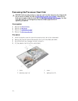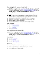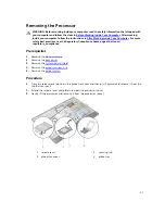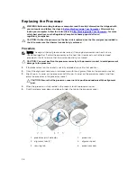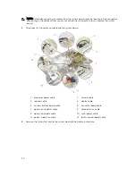
NOTE: Your computer’s Service Tag is stored in the system board. You must enter the Service Tag in
the BIOS setup program after you replace the system board.
Procedure
1.
Replace the side I/O bracket on the system board.
2.
Align the screw holes on the system board with the screw holes on the display-panel base.
3.
Replace the screws that secure the system board to the chassis.
4.
Route and connect all the cables to the connectors on the system board.
Post-requisites
1.
Replace the
coin-cell battery
.
2.
Replace the
wireless card
.
3.
Replace the
hard drive
.
4.
Replace the
processor
.
5.
Replace the
processor fan
.
6.
Replace the
processor heat-sink
.
7.
Replace the
I/O bracket
.
8.
Replace the
power-supply diagnostic board
.
9.
Replace the
VESA-mount bracket
.
10.
Replace the
system-board shield
.
11.
Replace the
memory module(s)
.
12.
Replace the
back cover
.
13.
Replace the
stand assembly
.
Entering the Service Tag in the BIOS
1.
Turn on the computer.
2.
Press <F2> when the DELL logo is displayed to enter the system setup program.
3.
Navigate to the main tab and enter the Service Tag in the Service Tag Input field.
Removing the Camera
WARNING: Before working inside your computer, read the safety information that shipped with
your computer and follow the steps in
Before Working Inside Your Computer
. After working
inside your computer, follow the instructions in
After Working Inside Your Computer
. For more
safety best practices, see the Regulatory Compliance home page at dell.com/
regulatory_compliance.
Prerequisites
1.
Remove the
stand assembly
.
2.
Remove the
back cover
.
3.
Remove the
memory module(s)
.
4.
Remove the
system-board shield
.
5.
Remove the
hard drive
.
6.
Remove the
VESA-mount bracket
.
52
Summary of Contents for vostro 23-3340
Page 1: ...Dell Vostro 23 3340 Owner s Manual Regulatory Model W10C Regulatory Type W10C001 ...
Page 7: ...System Setup Options 70 Flashing the BIOS 80 5 Specifications 81 6 Contacting Dell 84 ...
Page 63: ...20 Replace the memory module s 21 Replace the back cover 22 Replace the stand assembly 63 ...

