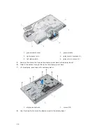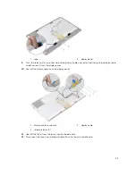
1.
screws (2)
2. right antenna module
3. left antenna module
4. securing tape
Replacing the Antenna
WARNING: Before working inside your computer, read the safety information that shipped with
your computer and follow the steps in
Before Working Inside Your Computer
. After working
inside your computer, follow the instructions in
After Working Inside Your Computer
. For more
safety best practices, see the Regulatory Compliance home page at dell.com/
regulatory_compliance.
Procedure
1.
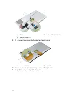
Align the screw holes on the antenna modules with the screw holes on the display bezel.
2.
Replace the screws that secure the antenna modules to the display bezel.
3.
Route the antenna cables through the routing guides on the display-panel base.
4.
Adhere the tape to secure the antenna modules to the display bezel.
Post-requisites
1.
Replace the
system board
.
2.
Replace the
coin-cell battery
.
3.
Replace the
wireless card
.
4.
Replace the
processor
.
5.
Replace the
processor fan
.
6.
Replace the
processor heat-sink
.
7.
Replace the
power-supply unit
.
8.
Replace the
power-supply fan
.
9.
Replace the
optical drive
.
10.
Replace the
I/O bracket
.
11.
Replace the
power-supply diagnostic board
.
12.
Replace the
converter board
.
13.
Replace the
control buttons board
.
14.
Replace the
VESA-mount bracket
.
15.
Replace the
hard drive
.
16.
Replace the
system-board shield
.
17.
Replace the
memory module(s)
.
18.
Replace the
back cover
.
19.
Replace the
stand assembly
.
56
Summary of Contents for vostro 23-3340
Page 1: ...Dell Vostro 23 3340 Owner s Manual Regulatory Model W10C Regulatory Type W10C001 ...
Page 7: ...System Setup Options 70 Flashing the BIOS 80 5 Specifications 81 6 Contacting Dell 84 ...
Page 63: ...20 Replace the memory module s 21 Replace the back cover 22 Replace the stand assembly 63 ...

