background image

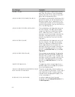
System Error Messages

System Message

Description

Alert! Previous attempts at booting this system 
have failed at checkpoint [nnnn]. For help in 
resolving this problem, please note this checkpoint 
and contact Dell Technical Support

The computer failed to complete the boot routine 
three consecutive times for the same error.

CMOS checksum error

Possible motherboard failure or Real-time clock 
(RTC) battery low.

CPU fan failure

CPU fan has failed

System fan failure

System fan has failed

Hard-disk drive failure

Possible hard disk drive failure during POST

Keyboard failure

Keyboard failure or loose cable. If reseating the 
cable does not solve the problem, replace the 
keyboard.

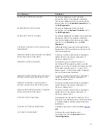
No boot device available

No bootable partition on hard disk drive, the hard 
disk drive cable is loose, or no bootable device 
exists.
• If the hard drive is your boot device, ensure that 

the cables are connected and that the drive is 

installed properly and partitioned as a boot 

device.

• Enter system setup and ensure that the boot 

sequence information is correct.

No timer tick interrupt

A chip on the system board might be 
malfunctioning or motherboard failure.

USB over current error

Disconnect the USB device. The USB device needs 
more power for it to function properly. Use an 
external power source to connect the USB device, 
or if the device has two USB cables, connect both 
of them.

CAUTION - Hard Drive SELF MONITORING 
SYSTEM has reported that a parameter has 
exceeded its normal operating range. Dell 
recommends that you back up your data regularly. 
A parameter out of range may or may not indicate 
a potential hard drive problem

S.M.A.R.T error, possible hard disk drive failure

69

Summary of Contents for vostro 23-3340

Page 1: ...Dell Vostro 23 3340 Owner s Manual Regulatory Model W10C Regulatory Type W10C001 ...

Page 2: ...problem WARNING A WARNING indicates a potential for property damage personal injury or death Copyright 2014 Dell Inc All rights reserved This product is protected by U S and international copyright and intellectual property laws Dell and the Dell logo are trademarks of Dell Inc in the United States and or other jurisdictions All other marks and names mentioned herein may be trademarks of their res...

Page 3: ...oving the Back Cover 14 Prerequisites 14 Procedure 14 Replacing the Back Cover 15 Procedure 16 Post requisites 16 Removing the Speaker Cover 16 Prerequisites 16 Procedure 16 Replacing the Speaker Cover 17 Procedure 17 Post requisites 17 Removing the Speakers 17 Prerequisites 17 Procedure 17 Replacing the Speakers 18 Procedure 18 Post requisites 18 Removing the Memory Module s 18 Prerequisites 19 P...

Page 4: ...ons Board 26 Prerequisites 26 Procedure 27 Replacing the Control Buttons Board 27 Procedure 27 Post requisites 27 Removing the Converter Board 28 Prerequisites 28 Procedure 28 Replacing the Converter Board 28 Procedure 29 Post requisites 29 Removing the Power Supply Diagnostic Board 29 Prerequisites 29 Procedure 29 Replacing the Power Supply Diagnostic Board 30 Procedure 30 Post requisites 30 Remo...

Page 5: ...al Drive 37 Prerequisites 37 Procedure 37 Replacing the Optical Drive 39 Procedure 39 Post requisites 39 Removing the Power Supply Fan 40 Prerequisites 40 Procedure 40 Replacing the Power Supply Fan 41 Procedure 41 Post requisites 41 Removing the Power Supply Unit 42 Prerequisites 42 Procedure 42 Replacing the Power Supply Unit 43 Procedure 43 Post requisites 43 Removing the Processor Heat Sink 44...

Page 6: ...ering the Service Tag in the BIOS 52 Removing the Camera 52 Prerequisites 52 Procedure 53 Replacing the Camera 54 Procedure 54 Post requisites 54 Removing the Antenna 54 Prerequisites 55 Procedure 55 Replacing the Antenna 56 Procedure 56 Post requisites 56 Removing the Display Panel 57 Prerequisites 57 Procedure 57 Replacing the Display Panel 61 Procedure 62 Post requisites 62 3 Troubleshooting Yo...

Page 7: ...System Setup Options 70 Flashing the BIOS 80 5 Specifications 81 6 Contacting Dell 84 ...

Page 8: ...and select Shut down In Windows 7 1 Click Start 2 Click Shut Down or 1 Click Start 2 Click the arrow in the lower right corner of the Start menu as shown below and then click Shut Down 2 Ensure that the computer and all attached devices are turned off If your computer and attached devices did not automatically turn off when you shut down your operating system press and hold the power button for ab...

Page 9: ... Replace any media cards discs and any other part s that you removed before working on your computer 4 Connect your computer and all attached devices to their electrical outlets 5 Turn on your computer 9 ...

Page 10: ...de Your Computer After working inside your computer follow the instructions in After Working Inside Your Computer For more safety best practices see the Regulatory Compliance home page at dell com regulatory_compliance Inside View of Your Computer 1 antennas 2 2 power supply unit 3 processor fan 4 processor heat sink 5 wireless card 6 coin cell battery 7 memory modules 2 8 side I O bracket 9 hard ...

Page 11: ...peaker cable connector 7 display cable connector 8 control buttons board cable connector 9 converter board cable connector 10 optical drive power cable connector 11 main power cable connector 12 hard drive connector 13 optical drive data cable connector 14 touch control board cable connector 15 power supply fan cable connector 16 video card fan cable connector 17 video card heat sink 18 processor ...

Page 12: ...est practices see the Regulatory Compliance home page at dell com regulatory_compliance Procedure 1 Press the stand release button to release the stand 2 Pivot the stand upward and remove the stand assembly away from the computer 1 stand release button If you need to remove either the stand base or stand riser from the stand assembly follow the steps below 3 Release the screw handle on the stand b...

Page 13: ...1 stand riser 2 stand base 3 captive thumbscrew 4 screw handle 5 Slide the stand base off the stand riser 1 stand riser 2 stand base 13 ...

Page 14: ...ow the steps below 3 Align the captive thumbscrew on the stand base with the screw hole on the stand riser and tighten it 4 Fold the screw handle on the stand base Removing the Back Cover WARNING Before working inside your computer read the safety information that shipped with your computer and follow the steps in Before Working Inside Your Computer After working inside your computer follow the in...

Page 15: ... back cover Replacing the Back Cover WARNING Before working inside your computer read the safety information that shipped with your computer and follow the steps in Before Working Inside Your Computer After working inside your computer follow the instructions in After Working Inside Your Computer For more safety best practices see the Regulatory Compliance home page at dell com regulatory_complian...

Page 16: ...ith your computer and follow the steps in Before Working Inside Your Computer After working inside your computer follow the instructions in After Working Inside Your Computer For more safety best practices see the Regulatory Compliance home page at dell com regulatory_compliance Prerequisites 1 Remove the stand assembly 2 Remove the back cover Procedure 1 Remove the screws that secure the speaker ...

Page 17: ...Replace the back cover 2 Replace the stand assembly Removing the Speakers WARNING Before working inside your computer read the safety information that shipped with your computer and follow the steps in Before Working Inside Your Computer After working inside your computer follow the instructions in After Working Inside Your Computer For more safety best practices see the Regulatory Compliance home...

Page 18: ...splay panel base 2 Replace the screws that secure the speakers to the display panel base 3 Route the speaker cables through the routing guide on the display panel base 4 Connect the speaker cable to the system board Post requisites 1 Replace the speaker cover 2 Replace the back cover 3 Replace the stand assembly Removing the Memory Module s WARNING Before working inside your computer read the safe...

Page 19: ...mory module shield off the system board shield 1 memory module shield 2 tabs 6 3 system board shield 2 Use your fingertips to carefully spread apart the securing clips on each end of the memory module connector until the memory module pops up 3 Remove the memory module from the memory module connector 19 ...

Page 20: ...ide your computer follow the instructions in After Working Inside Your Computer For more safety best practices see the Regulatory Compliance home page at dell com regulatory_compliance Procedure 1 Align the notch on the memory module with the tab on the memory module connector 2 Insert the memory module into the memory module connector and press the memory module down until it clicks into place NO...

Page 21: ...4 notch 5 securing clips 4 1 memory modules 2 3 Slide the tabs on the memory module shield under the tabs on the system board shield until the memory module shield is fully secured Post requisites 1 Replace the back cover 2 Replace the stand assembly 21 ...

Page 22: ... 2 Remove the back cover Procedure 1 Press the securing tab down and slide the system board shield to release it from the slots on the display panel base 2 Lift the system board shield off the computer 1 securing tab 2 system board shield Replacing the System Board Shield WARNING Before working inside your computer read the safety information that shipped with your computer and follow the steps in...

Page 23: ...er working inside your computer follow the instructions in After Working Inside Your Computer For more safety best practices see the Regulatory Compliance home page at dell com regulatory_compliance CAUTION Hard drives are fragile Exercise care when handling the hard drive CAUTION To avoid data loss do not remove the hard drive while the computer is in Sleep or On state Prerequisites 1 Remove the ...

Page 24: ...drive cage 3 Gently pry the hard drive bracket off the hard drive 1 hard drive 2 hard drive bracket 4 Remove the screws that secure the hard drive cage to the system board 5 Lift the hard drive cage off the system board 1 hard drive cage 2 screws 4 24 ...

Page 25: ...s on the hard drive assembly with the slots on the hard drive cage 5 Slide the hard drive assembly into the hard drive cage until it snaps into position Post requisites 1 Replace the system board shield 2 Replace the back cover 3 Replace the stand assembly Removing the VESA Mount Bracket WARNING Before working inside your computer read the safety information that shipped with your computer and fol...

Page 26: ...the screw holes on the display panel base 2 Replace the screws that secure the VESA mount bracket to the display panel base Post requisites 1 Replace the system board shield 2 Replace the back cover 3 Replace the stand assembly Removing the Control Buttons Board WARNING Before working inside your computer read the safety information that shipped with your computer and follow the steps in Before Wo...

Page 27: ...our computer and follow the steps in Before Working Inside Your Computer After working inside your computer follow the instructions in After Working Inside Your Computer For more safety best practices see the Regulatory Compliance home page at dell com regulatory_compliance Procedure 1 Connect the control buttons board cable to the connector on the control buttons board 2 Replace the control butto...

Page 28: ...ter board cable and display backlight cable from the connectors on the convertor board 2 Remove the screws that secure the convertor board to the display panel base 3 Lift the converter board off the display panel base 1 screws 2 2 display backlight cable 3 converter board 4 converter board cable Replacing the Converter Board WARNING Before working inside your computer read the safety information ...

Page 29: ...that shipped with your computer and follow the steps in Before Working Inside Your Computer After working inside your computer follow the instructions in After Working Inside Your Computer For more safety best practices see the Regulatory Compliance home page at dell com regulatory_compliance Prerequisites 1 Remove the stand assembly 2 Remove the back cover 3 Remove the system board shield 4 Remov...

Page 30: ...orking Inside Your Computer For more safety best practices see the Regulatory Compliance home page at dell com regulatory_compliance Procedure 1 Connect the power supply diagnostic board cable to the connector on the power supply diagnostic board 2 Align the screw hole on the power supply diagnostic board with the screw hole on the I O bracket 3 Replace the screw that secures the power supply diag...

Page 31: ...iance home page at dell com regulatory_compliance Prerequisites 1 Remove the stand assembly 2 Remove the back cover Procedure 1 Remove the screws that secure the microphone bracket to the microphones 2 Lift the microphone brackets off the display bezel 3 Press the securing tabs to release the microphones and lift the microphones out of their slots on the display bezel 4 Disconnect the microphone c...

Page 32: ...he screws that secure the microphone brackets to the microphones Post requisites 1 Replace the back cover 2 Replace the stand assembly Removing the Wireless Card WARNING Before working inside your computer read the safety information that shipped with your computer and follow the steps in Before Working Inside Your Computer After working inside your computer follow the instructions in After Workin...

Page 33: ...liance Procedure 1 Align the notch on the wireless card with the tab on the Mini Card slot 2 Slide the wireless card at an angle into the Mini Card slot 3 Press the other end of the wireless card down and replace the screw that secures the wireless card to the system board 4 Connect the antenna cables to the wireless card The following table provides the antenna cable color scheme for the wireless...

Page 34: ...ngs to default It is recommended that you note the BIOS settings before removing the coin cell battery Prerequisites 1 Replace the stand assembly 2 Replace the back cover 3 Replace the system board shield Procedure CAUTION Removing the coin cell battery resets the BIOS settings to default It is recommended that you note the BIOS settings before removing the coin cell battery 1 Locate the coin cell...

Page 35: ...hield 2 Replace the back cover 3 Replace the stand assembly Removing the I O Bracket WARNING Before working inside your computer read the safety information that shipped with your computer and follow the steps in Before Working Inside Your Computer After working inside your computer follow the instructions in After Working Inside Your Computer For more safety best practices see the Regulatory Comp...

Page 36: ...port 2 I O bracket Replacing the I O Bracket WARNING Before working inside your computer read the safety information that shipped with your computer and follow the steps in Before Working Inside Your Computer After working inside your computer follow the instructions in After Working Inside Your Computer For more safety best practices see the Regulatory Compliance home page at dell com regulatory_...

Page 37: ...lace the stand assembly Removing the Optical Drive WARNING Before working inside your computer read the safety information that shipped with your computer and follow the steps in Before Working Inside Your Computer After working inside your computer follow the instructions in After Working Inside Your Computer For more safety best practices see the Regulatory Compliance home page at dell com regul...

Page 38: ...ive 4 Remove the optical drive bracket from the optical drive 1 optical drive bezel 2 optical drive 3 optical drive bracket 4 screws 2 5 Disconnect the power cable and data cable from the system board 6 Remove the screws that secure the interposer to the display panel base 7 Remove the power cable and date cable from the routing guides on the display panel base 8 Lift the interposer off the displa...

Page 39: ...rposer with the screw holes on the display panel base 3 Replace the screws that secure the interposer to the display panel base 4 Connect the power and data cables to the system board 5 Align the screw holes on the optical drive bracket with the screw holes on the optical drive 6 Replace the screws that secure the optical drive bracket to the optical drive 7 Align the tabs on the optical drive bez...

Page 40: ...l com regulatory_compliance Prerequisites 1 Remove the stand assembly 2 Remove the back cover 3 Remove the system board shield 4 Remove the VESA mount bracket 5 Remove the power supply diagnostic board 6 Remove the I O bracket Procedure 1 Remove the screw that secures the power supply fan bracket to the display panel base 2 Lift the power supply fan bracket off the display panel base 1 screw 2 pow...

Page 41: ...ce Procedure 1 Connect the power supply fan cable to the power supply unit 2 Align the screw holes on the power supply fan with the screw holes on the display panel base 3 Replace the screws that secure the power supply fan to the display panel base 4 Align the screw holes on the power supply fan bracket with the screw holes on the display panel base 5 Replace the screw that secures the power supp...

Page 42: ...hield 4 Remove the VESA mount bracket 5 Remove the power supply diagnostic board 6 Remove the I O bracket Procedure 1 Disconnect the main power cable processor power cable and power supply fan cable from the system board 2 Remove the main power cable processor power cable and power supply fan cable from the routing guides on the display panel base 3 Remove the power port cable from the routing gui...

Page 43: ...to position 2 Align the screw hole and tabs on the power supply unit with the screw hole and tabs on the display panel base 3 Replace the screw that secures the power supply unit to the display panel base 4 Connect the power supply fan cable to the power supply unit 5 Route the power port cable through the routing guides on the display panel base 6 Route the main power cable processor power cable ...

Page 44: ...latory Compliance home page at dell com regulatory_compliance Prerequisites 1 Remove the stand assembly 2 Remove the back cover 3 Remove the system board shield 4 Remove the VESA mount bracket Procedure 1 Loosen the captive screws that secure the processor heat sink to the system board 2 Remove the screw that secures the processor heat sink to the display panel base 3 Peel off the Mylar from the p...

Page 45: ...he Mylar to the processor heat sink and fan 4 Replace the screw that secures the processor heat sink to the display panel base Post requisites 1 Replace the VESA mount bracket 2 Replace the system board shield 3 Replace the back cover 4 Replace the stand assembly Removing the Processor Fan WARNING Before working inside your computer read the safety information that shipped with your computer and f...

Page 46: ... For more safety best practices see the Regulatory Compliance home page at dell com regulatory_compliance Procedure 1 Align the screw holes on the processor fan with the screw holes on the display panel base 2 Adhere the Mylar on the processor fan and the processor heat sink 3 Replace the screws that secure the processor fan to the display panel base 4 Connect the processor fan cable to the system...

Page 47: ...liance home page at dell com regulatory_compliance Prerequisites 1 Remove the stand assembly 2 Remove the back cover 3 Remove the system board shield 4 Remove the processor heat sink 5 Remove the processor fan Procedure 1 Press the release lever down on the processor cover and then pull it outwards to release it from the tab that secures it 2 Extend the release lever completely to open the process...

Page 48: ... sink is replaced use the thermal pad provided in the kit to ensure that thermal conductivity is achieved CAUTION You must position the processor correctly in the processor socket to avoid permanent damage to the processor 1 If the release lever on the socket is not fully extended move it to that position 2 Orient the alignment notches on the processor with the alignment tabs on the processor sock...

Page 49: ... system board NOTE Replacing the system board removes any changes you have made to the BIOS using the BIOS setup program You must make the desired changes again after you replace the system board NOTE Before disconnecting the cables from the system board note the location of the connectors so that you can reconnect them correctly after you replace the system board Prerequisites 1 Remove the stand ...

Page 50: ...nnect all the cables connected to the system board 1 processor power cable 2 camera cable 3 speaker cable 4 display cable 5 control buttons board cable 6 converter board cable 7 optical drive power cable 8 video card fan cable 9 optical drive data cable 10 main power cable 11 power supply fan cable 12 touch control board cable 2 Remove the screws that secure the system board to the display panel b...

Page 51: ... bracket Replacing the System Board WARNING Before working inside your computer read the safety information that shipped with your computer and follow the steps in Before Working Inside Your Computer After working inside your computer follow the instructions in After Working Inside Your Computer For more safety best practices see the Regulatory Compliance home page at dell com regulatory_complianc...

Page 52: ...nt bracket 10 Replace the system board shield 11 Replace the memory module s 12 Replace the back cover 13 Replace the stand assembly Entering the Service Tag in the BIOS 1 Turn on the computer 2 Press F2 when the DELL logo is displayed to enter the system setup program 3 Navigate to the main tab and enter the Service Tag in the Service Tag Input field Removing the Camera WARNING Before working ins...

Page 53: ...processor 17 Remove the wireless card 18 Remove the coin cell battery 19 Remove the system board 20 Follow the procedure from step 1 to step 6 in Removing the Display Panel Procedure 1 Remove the screw that secures the ground cable and the camera module to the display bezel 2 Move the ground cable away to access the camera module 3 Carefully lift the camera module out of the display bezel 4 Discon...

Page 54: ...em board 3 Replace the coin cell battery 4 Replace the wireless card 5 Replace the processor 6 Replace the processor fan 7 Replace the processor heat sink 8 Replace the power supply unit 9 Replace the power supply fan 10 Replace the optical drive 11 Replace the I O bracket 12 Replace the power supply diagnostic board 13 Replace the converter board 14 Replace the control buttons board 15 Replace th...

Page 55: ...Remove the power supply fan 13 Remove the power supply unit 14 Remove the processor heat sink 15 Remove the processor fan 16 Remove the processor 17 Remove the wireless card 18 Remove the coin cell battery 19 Remove the system board Procedure 1 Peel the tape that secures the antenna modules to the display bezel 2 Remove the screws that secure the antenna modules to the display bezel 3 Note the ant...

Page 56: ...the antenna modules to the display bezel 3 Route the antenna cables through the routing guides on the display panel base 4 Adhere the tape to secure the antenna modules to the display bezel Post requisites 1 Replace the system board 2 Replace the coin cell battery 3 Replace the wireless card 4 Replace the processor 5 Replace the processor fan 6 Replace the processor heat sink 7 Replace the power s...

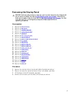
Page 57: ...A mount bracket 7 Remove the converter board 8 Remove the power supply diagnostic board 9 Remove the I O bracket 10 Remove the optical drive 11 Remove the power supply fan 12 Remove the power supply unit 13 Remove the processor heat sink 14 Remove the processor fan 15 Remove the processor 16 Remove the wireless card 17 Remove the coin cell battery 18 Remove the system board 19 Remove the speaker c...

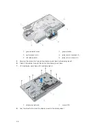
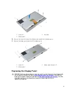
Page 58: ...se latch screws 4 5 Remove the screws that secure the display panel base to the display bezel 6 Slide all the cables through the slot on the display panel base 7 Lift the display panel base off the display bezel 1 display panel base 2 screws 15 8 Peel the tape that secures the display panel to the display bezel 58 ...

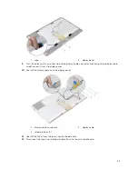
Page 59: ...ll the display cable to disconnect it from the display panel 10 Peel off the display cable from the display panel 1 display cable connector 2 display cable 3 release latches 2 11 Peel off the Mylar from the touch control board cable 12 Disconnect the touch control board cable from the touch control board 59 ...

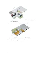
Page 60: ...ol board 13 Lift the latches and disconnect the flex cable from the display panel 1 connector latches 2 flex cable 14 Remove the screws that secure the display assembly to the display bezel 15 Gently lift the display assembly off the display bezel 60 ...

Page 61: ...s 2 3 display panel Replacing the Display Panel WARNING Before working inside your computer read the safety information that shipped with your computer and follow the steps in Before Working Inside Your Computer After working inside your computer follow the instructions in After Working Inside Your Computer For more safety best practices see the Regulatory Compliance home page at dell com regulato...

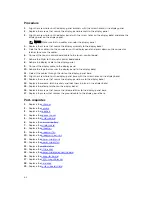
Page 62: ...bles through the slot on the display panel base 12 Align the screw holes on the display panel base with the screw holes on the display bezel 13 Replace the screws that secure the display panel base to the display bezel 14 Replace the release latch brackets and lock them in place in the display bezel 15 Replace the release latches on the display bezel 16 Replace the screws that secure the release l...

Page 63: ...20 Replace the memory module s 21 Replace the back cover 22 Replace the stand assembly 63 ...

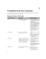
Page 64: ...re the electrical outlet is working by testing it with another device such as a lamp Blinking Amber Computer fails to complete POST or processor failure Remove and then reinstall any cards Remove and then reinstall the graphics card if applicable Ensure the power cable is connected to the motherboard and processor Steady Amber Computer is in standby or this is a computer fault error condition incl...

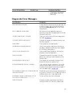
Page 65: ...all the memory modules or if necessary replace them DISK C FAILED INITIALIZATION The hard drive failed initialization Run the hard drive tests in the Dell Diagnostics DRIVE NOT READY The operation requires a hard drive in the bay before it can continue Install a hard drive in the hard drive bay ERROR READING PCMCIA CARD The computer cannot identify the ExpressCard Reinsert the card or try another ...

Page 66: ... the computer Shut down the computer remove the hard drive and boot the computer from an optical drive Then shut down the computer reinstall the hard drive and restart the computer If the problem persists try another drive Run the Hard Disk Drive tests in the Dell Diagnostics HARD DISK DRIVE READ FAILURE The hard drive may be defective Shut down the computer remove the hard drive and boot the comp...

Page 67: ...software you are attempting to run is conflicting with the operating system another program or a utility Shut down the computer wait 30 seconds and then restart it Try to run the program again If the error message still appears see the software documentation MEMORY DOUBLE WORD LOGIC FAILURE AT ADDRESS READ VALUE EXPECTING VALUE A memory module may be faulty or improperly seated Reinstall the memor...

Page 68: ... TIME OF DAY CLOCK LOST POWER System configuration settings are corrupted Connect your computer to an electrical outlet to charge the battery If the problem persists try to restore the data by entering the system setup program then immediately exit the program If the message reappears contact Dell TIME OF DAY CLOCK STOPPED The reserve battery that supports the system configuration settings may req...

Page 69: ...ard disk drive the hard disk drive cable is loose or no bootable device exists If the hard drive is your boot device ensure that the cables are connected and that the drive is installed properly and partitioned as a boot device Enter system setup and ensure that the boot sequence information is correct No timer tick interrupt A chip on the system board might be malfunctioning or motherboard failur...

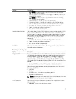
Page 70: ...ion Displays SLOT1 and SLOT2 Processor Information Displays Processor Type Core Count Processor ID Current Clock Speed Minimum Clock Speed Maximum Clock Speed Processor L2 Cache Processor L3 Cache HT Capable and 64 Bit Technology Device Information Displays SATA 0 SATA 1 LOM MAC Address Video Controller dGPU Video Controller Audio Controller Wi Fi Device and Bluetooth Device Boot Sequence Allows y...

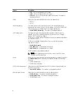
Page 71: ...t settings of the computer Apply Enables you to apply the settings Exit Exits and starts the computer Date Time Allows you to set the date and time The changes to the system date and time takes effect immediately Table 2 System Configuration Option Description Integrated NIC If you enable UEFI network stack UEFI network protocols will be available UEFI network allows pre os and early os networking...

Page 72: ...d to this port is enabled and available for operation system If USB port is disabled the operation system cannot see any device attached to this port Enable Boot Support Rear USB Ports Include options for 6 ports Side USB Potrs Include options for 2 ports All of the options are enabled by default NOTE USB keyboard and mouse always work in the BIOS setup irrespective of these settings Audio Allows ...

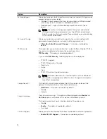
Page 73: ...delete the computer password previously called the primary password The drive does not have a password set by default Enter the old password Enter the new password Confirm the new password The successful changes in the password will take effect immediately Internal HDD 0 Password Allows you to set change or delete the password on the computer s internal hard disk drive HDD Successful changes to th...

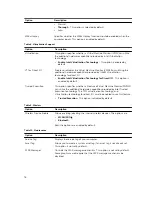
Page 74: ...s enabled and visible to the operating system TPM Security This option is disabled by default If you enable TPM Security following options will be displayed TPM ACPI support TPM PPI Deprivation Override Deactivate Active Clear TPM PPI Provision Override are shown NOTE Activation deactivation and clear options are not affected if you load the setup program s default values Changes to this option ta...

Page 75: ... admin password is set Enable Admin Setup Lockout This option is disabled by default HDD Protection Support Allows you to enable or disable the HDD Protection feature HDD Protection Support This option is disabled by default Table 4 Secure Boot Option Description Secure Boot Enable This option enables or disables the Secure Boot feature To enable the Secure Boot the computer has to be in UEFI boot...

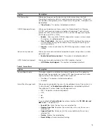
Page 76: ...Intel TurboBoost mode of the processor This option is enabled by default Disabled Does not allow the TurboBoost driver to increase the performance state of the processor above the standard performance Enabled Allows the Intel TurboBoost driver to increase the performance of the CPU or graphics processor Hyper Thread Control Allows you to enable or disable the Hyper Threading technology This option...

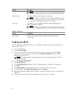
Page 77: ... USB Wake Support This option is enabled by default Wake on LAN WLAN This option allows the computer to power up from the off state when triggered by a special LAN signal Wake up from the Standby state is unaffected by this setting and must be enabled in the operating system This feature only works when the computer is connected to AC power supply This option is disabled by default Block Sleep Thi...

Page 78: ...tion is enabled by default Trusted Execution This option specifies whether a Measured Virtual Machine Monitor MVMM can utilize the additional hardware capabilities provided by Intel Trusted Execution technology The TPM virtualization technology and Virtualization technology for direct I O must be enabled to use this feature Trusted Execution This option is disabled by default Table 9 Wireless Opti...

Page 79: ...his option is relevant only when the Integrated NIC control in the System Configuration group is set to Enable with Cloud Desktop Client Address Method This option specifies how the client obtains its IP address The options are Static IP Uses the static IP address DHCP Obtains IP address using Dynamic Host Configuration Protocol DHCP This option is selected by default NOTE This option is relevant ...

Page 80: ...You may need to flash update the BIOS when an update is available or when you replace the system board To flash the BIOS 1 Turn on the computer 2 Go to dell com support 3 If you have your computer s Service Tag type your computer s Service Tag and click Submit If you do not have your computer s Service Tag click Detect My Product to allow automatic detection of the Service Tag NOTE If the Service ...

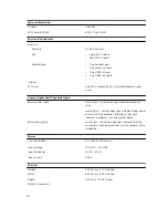
Page 81: ... Type Intel Pentium Dual Core 4th Generation Intel Core i3 4th Generation Intel Core i5 4th Generation L3 cache Up to 8 MB Memory Memory module connector two SODIMM slots Memory module capacity 2 GB 4 GB and 6 GB Type Dual channel DDR3L Minimum memory 2 GB Maximum memory 16 GB Video Video Type Integrated Intel HD 4600 Graphics Discrete AMD Radeon R7 A265 Integrated video memory Shared system memor...

Page 82: ...t white light solid white light indicates power on state amber light solid amber light indicates sleep stand by state of the computer blinking amber light indicates a problem with the system board drive activity light white light blinking white light indicates that the computer is reading data from or writing data to the hard drive Power Coin cell battery 3 V CR2032 lithium ion Input voltage 100 V...

Page 83: ...perature Operating 5 C to 35 C 41 F to 95 F Storage 40 C to 65 C 40 F to 149 F Relative humidity 20 to 80 non condensing Altitude Operating 15 20 m to 2000 m 50 ft to 6560 ft Storage 15 20 m to 10 668 m 50 ft to 35 000 ft Airborne contaminant level G1 as defined by ISA S71 04 1985 83 ...

Page 84: ...ed support and service options Availability varies by country and product and some services may not be available in your area To contact Dell for sales technical support or customer service issues 1 GO to dell com support 2 Select your support category 3 Verify your country or region in the Choose a Country Region drop down list at the top of page 4 Select the appropriate service or support link b...

Reviews: