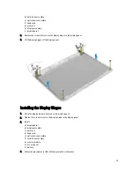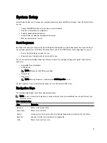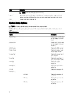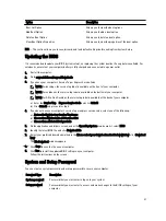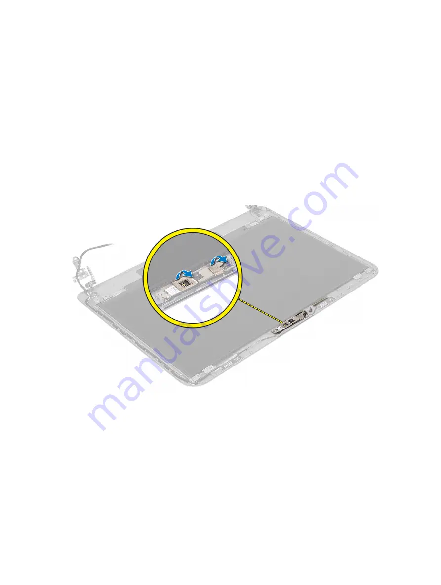
Removing the Camera Module
1.
Follow the procedures in
Before Working Inside Your Computer
.
2.
Remove:
a) battery
b) access panel
c) memory module
d) hard-drive assembly
e) optical-drive assembly
f) keyboard
g) palmrest
h) display assembly
i) display bezel
3.
Disconnect the camera cable from the connector on the camera module and lift the camera off the display
assembly.
34
Summary of Contents for Vostro 2421
Page 1: ...Dell Vostro 2421 Owner s Manual Regulatory Model P37G Regulatory Type P37G001 ...
Page 4: ...4 ...
Page 8: ...8 ...
Page 23: ...4 Disconnect the following cables a display b DC In Port c speaker d I O board 23 ...
Page 36: ...36 ...
Page 44: ...44 ...
Page 48: ...48 ...
Page 54: ...54 ...

