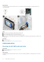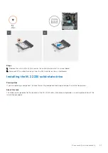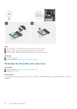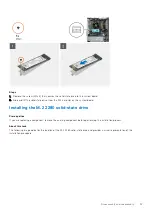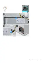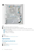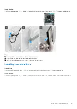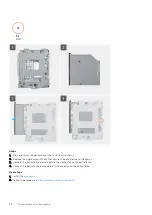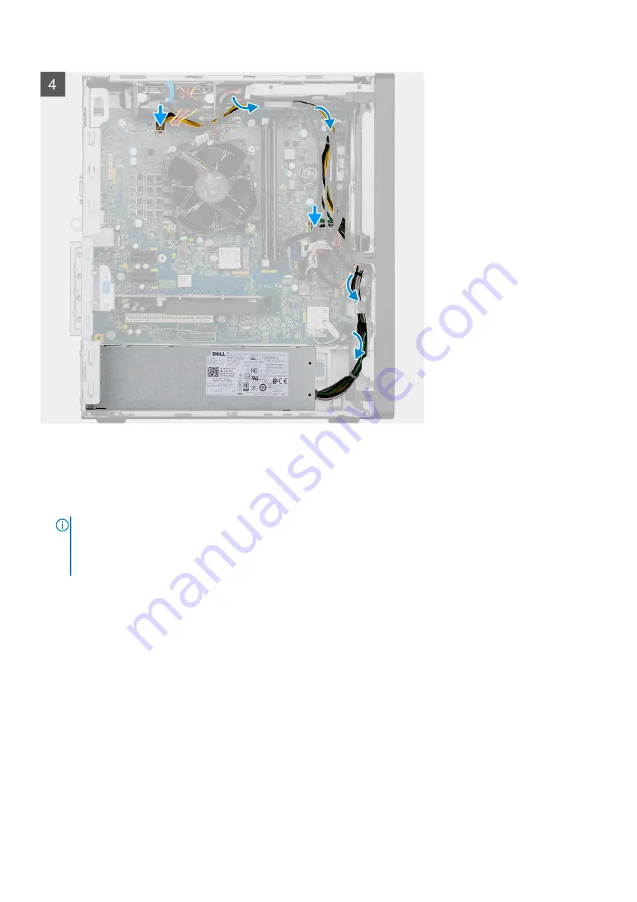
Steps
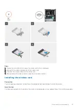
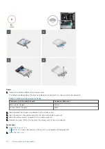
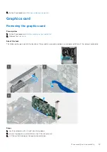
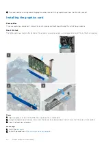
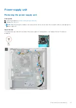
1. Place and slide the power supply into its slot on the chassis.
2. Replace the three (#6-32) screws to secure the power-supply unit to the chassis.
3. Route the power cable through the routing guides on the chassis and connect the power cables to their respective
connectors on the system board.
NOTE:
The power-supply cable is connected to the system board at two locations and supply power to the following
components at the two location:
●
Processor - ATX CPU connector
●
System board - ATX SYS connector
Next steps
1. Install the
.
After working inside your computer
.
Optical drive
Removing the optical drive
Prerequisites
Before working on your computer
.
2. Remove the
.
3. Remove the
.
44
Disassembly and reassembly
Summary of Contents for Vostro 3881
Page 1: ...Vostro 3881 Service Manual Regulatory Model D29M Regulatory Type D29M002 August 2021 Rev A01 ...
Page 3: ...1 Major components of your system 3 ...
Page 4: ...Major components of your system 4 Major components of your system ...
Page 43: ...Disassembly and reassembly 43 ...
Page 60: ...60 Disassembly and reassembly ...
Page 63: ...Disassembly and reassembly 63 ...

