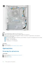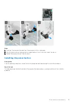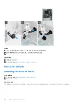
Steps
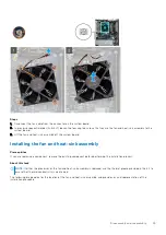
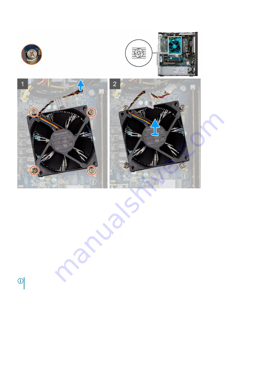
1. Disconnect the fan cable from the connector on the system board.
2. In a reverse sequential order (4>3>2>1) loosen the four captive screws that secure the fan and heat-sink assembly to the
system board.
3. Lift the fan and heat-sink assembly off the system board.
Installing the fan and heat-sink assembly
Prerequisites
If you are replacing a component, remove the existing component before performing the installation process.
About this task
NOTE:
If either the processor or the fan and heat-sink assembly is replaced, use the thermal grease provided in the kit to
ensure that thermal conductivity is maintained.
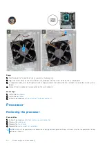
The following image indicates the location of the fan and heat-sink assembly, and provides a visual representation of the
installation procedure.
Disassembly and reassembly
49
Summary of Contents for Vostro 3881
Page 1: ...Vostro 3881 Service Manual Regulatory Model D29M Regulatory Type D29M002 August 2021 Rev A01 ...
Page 3: ...1 Major components of your system 3 ...
Page 4: ...Major components of your system 4 Major components of your system ...
Page 43: ...Disassembly and reassembly 43 ...
Page 60: ...60 Disassembly and reassembly ...
Page 63: ...Disassembly and reassembly 63 ...

