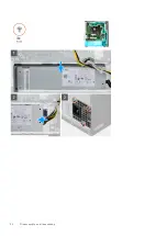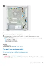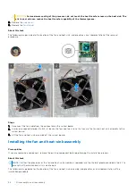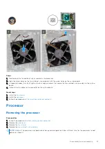
Steps
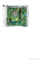
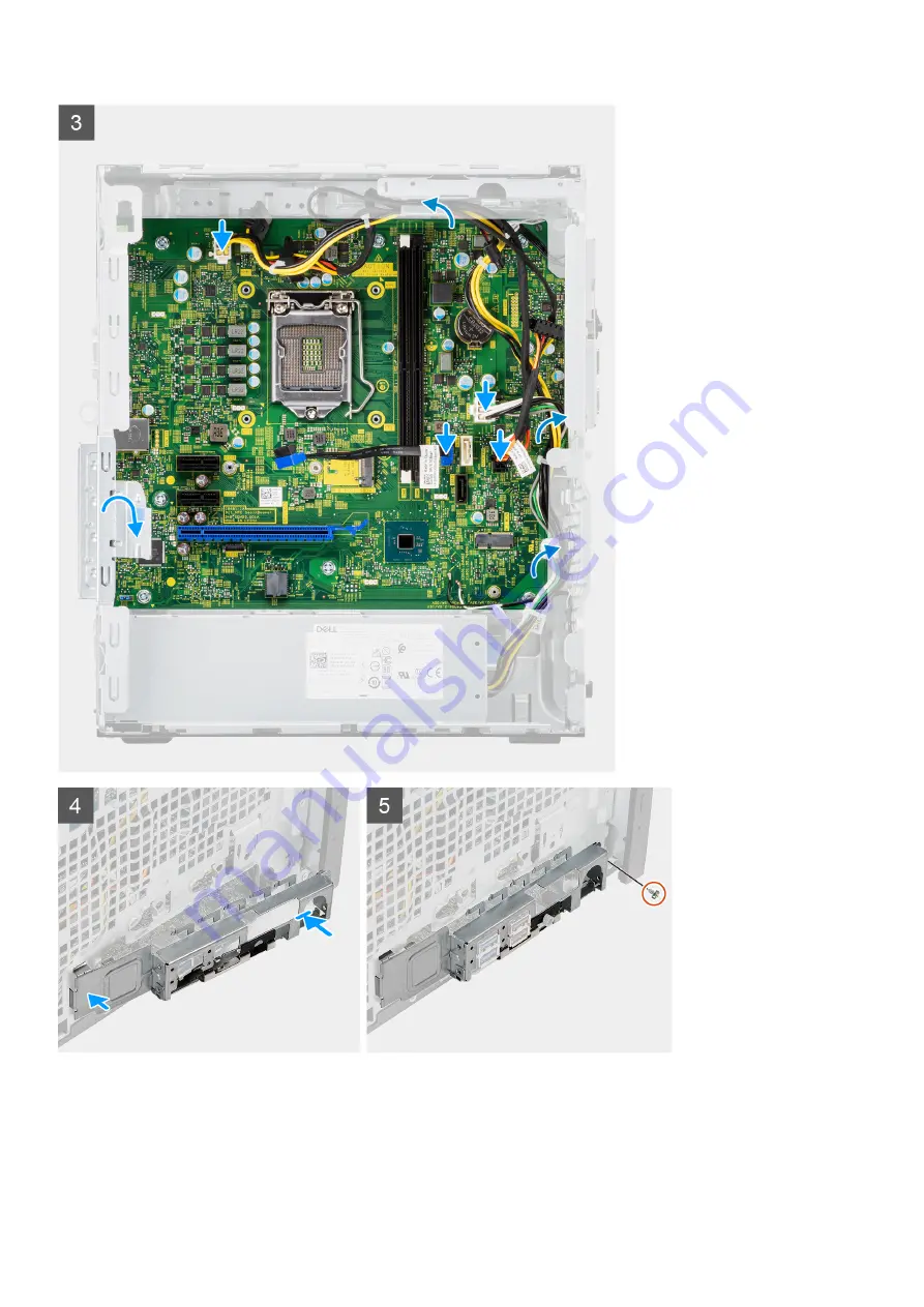
1. Place the system board onto the chassis and ensure that the chassis screw holes align with the ones on the system board.
2. Replace the eight screws (#6-32) that secure the system board to the chassis.
3. Using the routing points on the chassis, route and reconnect the following cables to the connectors on the system board:
●
Power-supply cables
48
Disassembly and reassembly
Summary of Contents for Vostro 3890
Page 1: ...Vostro 3890 Service Manual Regulatory Model D29M Regulatory Type D29M004 April 2021 Rev A00 ...
Page 8: ...Major components of your system 1 Side cover 8 Disassembly and reassembly ...
Page 34: ...34 Disassembly and reassembly ...
Page 44: ...44 Disassembly and reassembly ...
Page 47: ...Disassembly and reassembly 47 ...

