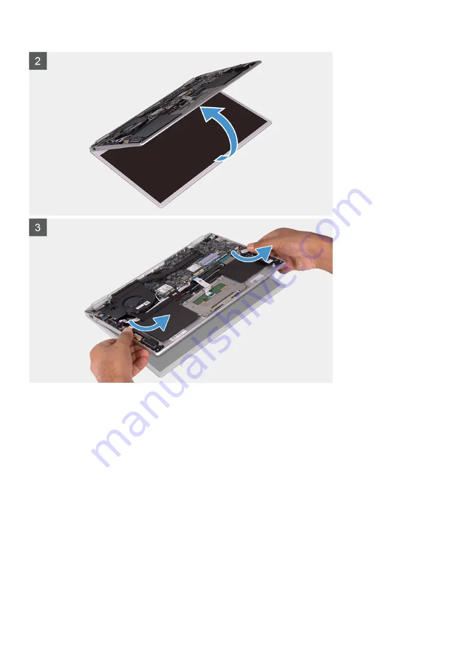
1. Remove the two screws (M2x4) that secure the left and right display hinges to the I/O board and palm-rest and keyboard assembly.
2. Peel the tape and using the pull tab, remove the display cable from the system board.
3. Open the display assembly as far as possible.
4. Remove the palm-rest and keyboard assembly off the display assembly.
34
Removing and installing components
Summary of Contents for Vostro 5391
Page 1: ...Dell Vostro 5391 Service Manual Regulatory Model P114G Regulatory Type P114G001 ...
Page 33: ...Removing and installing components 33 ...
Page 43: ...Removing and installing components 43 ...
Page 45: ...Removing and installing components 45 ...
Page 51: ...Removing and installing components 51 ...


