


Steps
1. Press and hold the securing tab on the chassis and slide the power-supply unit into the chassis until it snaps into position.
2. Replace the three (6-32) screws that secure the power-supply unit to the chassis.
3. Route the power cable through the routing guides on the chassis and connect the power cable to connector on the powered
graphics card.
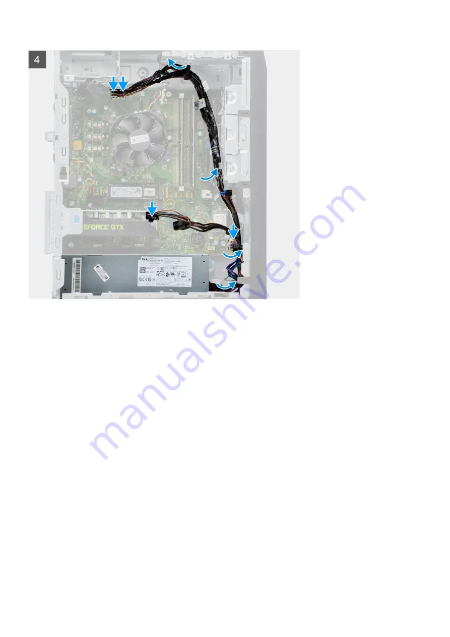
4. Route the power cable through the routing guides on the chassis and connect the power cables to the connectors on the
system board.
5. Connect the power cable to the power-supply unit.
Next steps
1. Install the
.
After working inside your computer
.
Heatsink assembly
Removing the heatsink assembly
Prerequisites
Before working inside your computer
.
2. Remove the
.
About this task
The following images indicate the location of the heatsink assembly and provide a visual representation of the removal
procedure.
Disassembly and reassembly
37
Summary of Contents for Vostro 5890
Page 1: ...Vostro 5890 Service Manual Regulatory Model D28M Regulatory Type D28M004 August 2021 Rev A01 ...
Page 36: ...36 Disassembly and reassembly ...
Page 44: ...44 Disassembly and reassembly ...
Page 45: ...Disassembly and reassembly 45 ...
Page 47: ...Disassembly and reassembly 47 ...
Page 48: ...48 Disassembly and reassembly ...
Page 49: ...Disassembly and reassembly 49 ...


