background image

26

  |  Removing 

the 

Coin-Cell 

Battery

4

Peel the coin-cell battery off the keyboard.

5

Lift the coin-cell battery along with its cable off the keyboard. 

1

coin-cell-battery cable

2

coin-cell battery

2

1

book.book  Page 26  Tuesday, October 23, 2012  12:44 AM

Summary of Contents for XPS 12

Page 1: ...Dell XPS 12 Owner s Manual Computer model XPS 9Q23 Regulatory model P20S Regulatory type P20S001 ...

Page 2: ...a potential for property damage personal injury or death ____________________ 2012 Dell Inc Trademarks used in this text Dell the DELL logo and XPS are trademarks of Dell Inc Microsoft Windows and the Windows start button logo are either trademarks or registered trademarks of Microsoft corporation in the United States and or other countries Bluetooth is a registered trademark owned by Bluetooth SI...

Page 3: ... 10 Replacing the Base Cover 12 Procedure 12 Removing the Battery 13 Prerequisites 13 Procedure 13 Replacing the Battery 14 Procedure 14 Postrequisites 14 Removing the Wireless Mini Card 15 Prerequisites 15 Procedure 15 Replacing the Wireless Mini Card 17 Procedure 17 Postrequisites 17 Removing the mSATA Card 19 Prerequisites 19 Procedure 19 Replacing the mSATA Card 21 Procedure 21 Postrequisites ...

Page 4: ... Coin Cell Battery 27 Procedure 27 Postrequisites 27 Removing the Fan 28 Prerequisites 28 Procedure 28 Replacing the Fan 30 Procedure 30 Postrequisites 30 Removing the Processor Heat Sink 31 Prerequisites 31 Procedure 31 Replacing the Processor Heat Sink 32 Procedure 32 Postrequisites 32 Removing the I O Board 33 Prerequisites 33 Procedure 33 Replacing the I O Board 35 Procedure 35 Postrequisites ...

Page 5: ... 42 Postrequisites 42 Entering the Service Tag in the BIOS 42 Removing the Display Assembly 43 Prerequisites 43 Procedure 43 Replacing the Display Assembly 46 Procedure 46 Postrequisites 46 Removing the Display Back Cover 47 Prerequisites 47 Procedure 47 Replacing the Display Back Cover 49 Procedure 49 Postrequisites 49 Removing the Camera Module 50 Prerequisites 50 Procedure 50 Replacing the Came...

Page 6: ...Button Board 56 Procedure 56 Postrequisites 56 Removing the Display Panel 57 Prerequisites 57 Procedure 57 Replacing the Display Panel 61 Procedure 61 Postrequisites 61 Removing the Keyboard 62 Prerequisites 62 Procedure 63 Replacing the Keyboard 65 Procedure 65 Postrequisites 65 Flashing the BIOS 66 ...

Page 7: ...d devices from their electrical outlets 4 Disconnect all telephone cables network cables and attached devices from your computer 5 Slide and hold the power switch for 5 seconds after the computer is unplugged to ground the system board Safety Instructions Use the following safety guidelines to protect your computer from potential damage and ensure your personal safety WARNING Before working inside...

Page 8: ...ty which could harm internal components CAUTION When you disconnect a cable pull on its connector or on its pull tab not on the cable itself Some cables have connectors with locking tabs or thumb screws that you must disengage before disconnecting the cable When disconnecting cables keep them evenly aligned to avoid bending any connector pins When connecting cables ensure that the connectors and p...

Page 9: ...main inside your computer Connect any external devices cables cards and any other part s you removed before working on your computer Connect your computer and all attached devices to their electrical outlets CAUTION Before turning on your computer replace all screws and ensure that no stray screws remain inside the computer Failure to do so may damage your computer Turn on your computer ...

Page 10: ...your computer follow the instructions in After Working Inside Your Computer on page 9 For additional safety best practices information see the Regulatory Compliance Homepage at dell com regulatory_compliance Procedure 1 Close the display and turn the computer over 2 Turn the system badge over and place it on the base cover 3 Remove the screws that secure the base cover to the palm rest assembly 1 ...

Page 11: ...arting from the side of the computer carefully pry the base cover 5 Carefully lift the base cover at an angle and slide the base cover to release the power switch slot from the power switch 1 screws 11 2 base cover 1 base cover 1 2 1 ...

Page 12: ... Your Computer on page 9 For additional safety best practices information see the Regulatory Compliance Homepage at dell com regulatory_compliance Procedure 1 Slide the power switch slot into the power switch and place the base cover on the palm rest assembly 2 Snap the base cover into place 3 Replace the screws that secure the base cover to the palm rest assembly 4 Turn the system badge over and ...

Page 13: ...nal safety best practices information see the Regulatory Compliance Homepage at dell com regulatory_compliance Prerequisites Remove the base cover See Removing the Base Cover on page 10 Procedure 1 Disconnect the battery cable from the system board connector 2 Remove the screws that secure the battery to the palm rest assembly 3 Lift the battery along with its cable off the palm rest assembly 4 Sl...

Page 14: ...ge 9 For additional safety best practices information see the Regulatory Compliance Homepage at dell com regulatory_compliance Procedure 1 Align the screw holes on the battery with the screw holes on the palm rest assembly 2 Replace the screws that secure the battery to the palm rest assembly 3 Connect the battery cable to the system board connector Postrequisites 1 Replace the base cover See Repl...

Page 15: ...ctices information see the Regulatory Compliance Homepage at dell com regulatory_compliance If you ordered a wireless mini card with your computer the card is already installed Prerequisites 1 Remove the base cover See Removing the Base Cover on page 10 2 Remove the battery See Removing the Battery on page 13 Procedure 1 Disconnect the antenna cables from connectors on the wireless mini card 2 Rem...

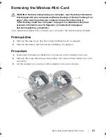
Page 16: ...16 Removing the Wireless Mini Card 1 antenna cables 2 2 wireless mini card 3 screw ...

Page 17: ...excessive force you may damage the connector CAUTION The connectors are keyed to ensure correct insertion If you feel resistance check the connectors on the wireless mini card and on the wireless system board connector and realign the wireless mini card CAUTION To avoid damage to the wireless mini card never place cables under the wireless mini card 2 Insert the wireless mini card at a 45 degree a...

Page 18: ...18 Replacing the Wireless Mini Card 3 Follow the instructions in After Working Inside Your Computer on page 9 ...

Page 19: ...rking Inside Your Computer on page 9 For additional safety best practices information see the Regulatory Compliance Homepage at dell com regulatory_compliance Prerequisites 1 Remove the base cover See Removing the Base Cover on page 10 2 Remove the battery See Removing the Battery on page 13 Procedure 1 Peel the mylar from the mSATA card 2 Remove the screw that secures the mSATA card to the mSATA ...

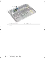
Page 20: ...20 Removing the mSATA Card 1 mSATA card connector 2 mSATA card 3 screw 3 2 1 ...

Page 21: ...mpliance Homepage at dell com regulatory_compliance Procedure 1 Align the notch on the mSATA card with the tab on the mSATA card connector 2 Insert the mSATA card at a 45 degree angle into the mSATA card connector 3 Press the other end of the mSATA card down and replace the screw that secures the mSATA card to the mSATA card connector 4 Adhere the mylar to the mSATA card Postrequisites 1 Replace t...

Page 22: ...compliance Prerequisites 1 Remove the base cover See Removing the Base Cover on page 10 2 Remove the battery See Removing the Battery on page 13 Procedure 1 Lift the connector latch and disconnect the touchpad cable from the system board connector 2 Move the touchpad cable away from the speakers cable 3 Disconnect the speaker cable from the I O board connector 4 Remove the screws that secure the s...

Page 23: ...Removing the Speakers 23 1 touchpad cable connector 2 touchpad cable 3 screws 4 4 palm rest assembly 5 speakers 2 6 speakers cable 7 speakers cable connector 5 4 3 7 6 1 2 ...

Page 24: ...osts on the palm rest assembly to place the speakers in position NOTE Ensure that the speakers are secured by the alignment posts 2 Replace the screws that secure the speakers to the palm rest assembly 3 Route the speaker cable through the routing guides on the palm rest assembly 4 Connect the speakers cable to the I O board connector 5 Slide the touchpad cable into the system board connector and ...

Page 25: ...tory Compliance Homepage at dell com regulatory_compliance CAUTION Removing the coin cell battery resets the BIOS settings to default It is recommended that you note the BIOS settings before removing the coin cell battery Prerequisites 1 Remove the base cover See Removing the Base Cover on page 10 2 Remove the battery See Removing the Battery on page 13 Procedure 1 Disconnect the I O board cable f...

Page 26: ...26 Removing the Coin Cell Battery 4 Peel the coin cell battery off the keyboard 5 Lift the coin cell battery along with its cable off the keyboard 1 coin cell battery cable 2 coin cell battery 2 1 ...

Page 27: ...ell com regulatory_compliance WARNING The battery may explode if installed incorrectly Replace the battery only with the same or equivalent type Discard used batteries according to the manufacturer s instructions Procedure 1 Adhere the coin cell battery to the keyboard 2 Route the coin cell battery cable through the routing guides 3 Connect the coin cell battery cable and I O board cable to the sy...

Page 28: ...see the Regulatory Compliance Homepage at dell com regulatory_compliance Prerequisites 1 Remove the base cover See Removing the Base Cover on page 10 2 Remove the battery See Removing the Battery on page 13 Procedure 1 Disconnect the I O board cable from the I O board and system board and lift the cable away from the computer 2 Note the coin cell battery cable routing and remove the cable from the...

Page 29: ...Removing the Fan 29 5 Slide and lift the fan along with its cable away from the keyboard 1 fan 2 screws 2 3 fan cable 2 1 3 ...

Page 30: ...y_compliance Procedure 1 Slide the tab on the fan under the heat sink and align the screw holes on the fan with the screw holes on the keyboard 2 Replace the screws that secure the fan to the keyboard 3 Connect the fan cable to the system board connector 4 Route the coin cell battery cable through the routing guides 5 Connect the I O board cable to the connectors on the I O board and system board ...

Page 31: ...age 9 For additional safety best practices information see the Regulatory Compliance Homepage at dell com regulatory_compliance Prerequisites 1 Remove the base cover See Removing the Base Cover on page 10 2 Remove the battery See Removing the Battery on page 13 Procedure 1 In sequential order indicated on the processor heat sink loosen the captive screws that secure the processor heat sink to the ...

Page 32: ...rmal grease can be reused if the original system board and heat sink are reinstalled together If either the system board or the heat sink is replaced use the thermal pad provided in the kit to ensure that thermal conductivity is achieved 1 Align the captive screws on the processor heat sink with the screw holes on the system board 2 In sequential order indicated on the processor heat sink tighten ...

Page 33: ...follow the instructions in After Working Inside Your Computer on page 9 For additional safety best practices information see the Regulatory Compliance Homepage at dell com regulatory_compliance Prerequisites 1 Remove the base cover See Removing the Base Cover on page 10 2 Remove the battery See Removing the Battery on page 13 Procedure 1 Using the pull tab disconnect the I O board cable 2 Disconne...

Page 34: ... Board 3 Remove the screws that secure the I O board to the palm rest assembly 4 Lift the I O board away from the palm rest assembly 1 I O board cable 2 pull tab 3 speakers cable connector 4 I O board 5 screws 2 1 3 5 4 2 ...

Page 35: ...egulatory_compliance Procedure NOTE The power switch must be in its default position before replacing the I O board 1 Align the screw holes on the I O board with the screw holes on the palm rest assembly 2 Replace the screws that secure the I O board to the palm rest assembly 3 Connect the speakers cable to the connector on the I O board 4 Connect the I O board cable to the connector on the I O bo...

Page 36: ...isites 1 Remove the base cover See Removing the Base Cover on page 10 2 Remove the battery See Removing the Battery on page 13 Procedure 1 Disconnect the antenna cables from the wireless mini card See Removing the Wireless Mini Card on page 15 2 Note the antenna cable routing and remove the antenna cables from the routing guides on the system board 3 Disconnect the power adapter port cable from th...

Page 37: ...rocedure 1 Slide the power adapter port cable under the display hinge 2 Align the screw hole on the power adapter port with the screw hole on the palm rest assembly 3 Replace the screw that secures the power adapter port to the palm rest assembly 4 Connect the power adapter port cable to the system board connector 5 Route the antenna cables through the routing guide on the system board 6 Connect t...

Page 38: ...additional safety best practices information see the Regulatory Compliance Homepage at dell com regulatory_compliance Prerequisites 1 Remove the base cover See Removing the Base Cover on page 10 2 Remove the battery See Removing the Battery on page 13 3 Remove the wireless mini card See Removing the Wireless Mini Card on page 15 4 Remove the mSATA card See Removing the mSATA Card on page 19 5 Remo...

Page 39: ...ving the Coin Cell Battery on page 25 2 Disconnect the power adapter port cable from the system board 3 Using the pull tabs disconnect the display cables from the system board 4 Lift the connector latches and using the pull tabs disconnect the touchpad cable and keyboard backlit cable from the system board connectors 5 Remove the antenna cables from the routing guide on the system board See Removi...

Page 40: ...40 Removing the System Board 7 Carefully lift the system board and turn it over 8 Lift the connector latch and disconnect the keyboard cable from the system board connector 1 screws 4 1 1 ...

Page 41: ...Removing the System Board 41 9 Lift the system board off the palm rest assembly 1 keyboard cable ...

Page 42: ...y cable 5 Connect the power adapter port cable to the system board 6 Connect the touchscreen cable and display cable to the system board 7 Route the antenna cables through the routing guide on the system board 8 Slide the touchpad cable and keyboard backlit cable into their connectors on the system board and press down on the connector latches to secure the cables Postrequisites 1 Replace the proc...

Page 43: ... Computer on page 9 For additional safety best practices information see the Regulatory Compliance Homepage at dell com regulatory_compliance Prerequisites 1 Remove the base cover See Removing the Base Cover on page 10 2 Remove the battery See Removing the Battery on page 13 Procedure 1 Disconnect the power adapter port cable from the system board 2 Using the pull tabs disconnect the display cable...

Page 44: ...mbly to the palm rest assembly 5 Carefully lift the palm rest assembly at an angle and slide the palm rest assembly to release the tabs on the palm rest assembly from the display hinges 1 power adapter port cable 2 display cables 3 antenna cables 1 screws 6 2 palm rest assembly 1 2 ...

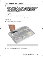
Page 45: ...Removing the Display Assembly 45 1 display hinges 2 1 ...

Page 46: ...he Regulatory Compliance Homepage at dell com regulatory_compliance Procedure 1 Slide the tabs on the palm rest assembly into the slots on the display hinges 2 Replace the screws that secure the display assembly to the palm rest assembly 3 Connect the antenna cables to the wireless mini card 4 Connect the power adapter port cable and display cables to the system board Postrequisites 1 Replace the ...

Page 47: ...king Inside Your Computer on page 9 For additional safety best practices information see the Regulatory Compliance Homepage at dell com regulatory_compliance Prerequisites 1 Remove the base cover See Removing the Base Cover on page 10 2 Remove the battery See Removing the Battery on page 13 Procedure 1 Turn the computer over and open the display as far as possible 2 Rotate the display panel to a 4...

Page 48: ...48 Removing the Display Back Cover 4 Carefully pry the display back cover off the display panel 1 screws 8 2 display back cover 1 screws 8 2 display back cover 1 2 ...

Page 49: ...omputer on page 9 For additional safety best practices information see the Regulatory Compliance Homepage at dell com regulatory_compliance Procedure 1 Place the display back cover on the display panel and snap it into place 2 Replace the screws that secure the display back cover to the display panel Postrequisites 1 Replace the battery See Replacing the Battery on page 14 2 Replace the base cover...

Page 50: ...ctices information see the Regulatory Compliance Homepage at dell com regulatory_compliance Prerequisites 1 Remove the base cover See Removing the Base Cover on page 10 2 Remove the battery See Removing the Battery on page 13 3 Remove the display back cover See Removing the Display Back Cover on page 47 Procedure 1 Remove the screws that secure the camera module to the display panel 2 Turn the cam...

Page 51: ...Removing the Camera Module 51 1 screws 2 2 camera cable connector 3 camera module ...

Page 52: ...Regulatory Compliance Homepage at dell com regulatory_compliance Procedure 1 Connect the camera cable to the connector on the camera module 2 Use the alignment posts to place the camera module on the display panel 3 Replace the screws that secure the camera module to the display panel Postrequisites 1 Replace the display back cover See Replacing the Display Back Cover on page 49 2 Replace the batt...

Page 53: ...Replacing the Camera Module 53 ...

Page 54: ...tion see the Regulatory Compliance Homepage at dell com regulatory_compliance Prerequisites 1 Remove the base cover See Removing the Base Cover on page 10 2 Remove the battery See Removing the Battery on page 13 3 Remove the display back cover See Removing the Display Back Cover on page 47 Procedure 1 Remove the screws that secure the windows button board to the display panel 2 Turn the windows bu...

Page 55: ...Removing the Windows Button Board 55 1 screws 2 2 windows button board cable connector 3 windows button board ...

Page 56: ... Compliance Homepage at dell com regulatory_compliance Procedure 1 Connect the windows button board cable to the connector on the windows button board 2 Use the alignment posts to place the windows button board on the display panel 3 Replace the screws that secure the windows button board to the display panel Postrequisites 1 Replace the display back cover See Replacing the Display Back Cover on p...

Page 57: ...ces information see the Regulatory Compliance Homepage at dell com regulatory_compliance Prerequisites 1 Remove the base cover See Removing the Base Cover on page 10 2 Remove the battery See Removing the Battery on page 13 3 Remove the display back cover See Removing the Display Back Cover on page 47 4 Remove the camera module See Removing the Camera Module on page 50 5 Remove the windows button b...

Page 58: ...58 Removing the Display Panel 2 Peel off the display cable from the display panel ...

Page 59: ...moving the Display Panel 59 3 Remove the screws that secure the display panel to the display bezel 4 Slide and lift the display panel off the display bezel 1 display panel 2 display bezel 3 screws 4 1 3 2 ...

Page 60: ...60 Removing the Display Panel ...

Page 61: ...les on the display panel with the screw holes on the display bezel 2 Replace the screws that secure the display panel to the display bezel 3 Adhere the display cable to the display panel 4 Connect the display cable to the connector on the display panel Postrequisites 1 Replace the windows button board See Replacing the Windows Button Board on page 56 2 Replace the camera module See Replacing the C...

Page 62: ... Begin on page 7 After working inside your computer follow the instructions in After Working Inside Your Computer on page 9 For additional safety best practices information see the Regulatory Compliance Homepage at dell com regulatory_compliance Prerequisites 1 Remove the I O board See Removing the I O Board on page 33 2 Remove the system board See Removing the System Board on page 38 ...

Page 63: ...ket and mSATA bracket off the keyboard CAUTION The keycaps on the keyboard are fragile easily dislodged and time consuming to replace Be careful when removing and handling the keyboard 3 Remove the screws that secure the keyboard to the palm rest assembly 4 Lift the keyboard off the palm rest assembly 1 mSATA bracket 2 screws 3 3 WLAN bracket 2 1 3 ...

Page 64: ...64 Removing the Keyboard 1 screws 24 1 ...

Page 65: ...egulatory_compliance Procedure 1 Align the screw holes on the keyboard with the screw holes on the palm rest assembly 2 Replace the screws that secure the keyboard to the palm rest assembly 3 Align the screw holes on the WLAN bracket and mSATA bracket with the screw holes on the palm rest assembly 4 Replace the screws that secure the WLAN bracket and mSATA bracket to the palm rest assembly Postreq...

Page 66: ...ubmit and proceed to step 4 If you do not have your computer s Service Tag or Express Service Code a Select one of the following options Automatically detect my Service Tag for me Choose from My Products and Services List Choose from a list of all Dell products b Click Continue and follow the instructions on the screen 4 A list of results appears on the screen Click BIOS 5 Click Download File to d...

Reviews: