Steps
1. Align the screw holes on the system board with the screw holes on the palm-rest and keyboard assembly.
2. Replace the three screws (M2x4) that secure the system board to the palm-rest and keyboard assembly.
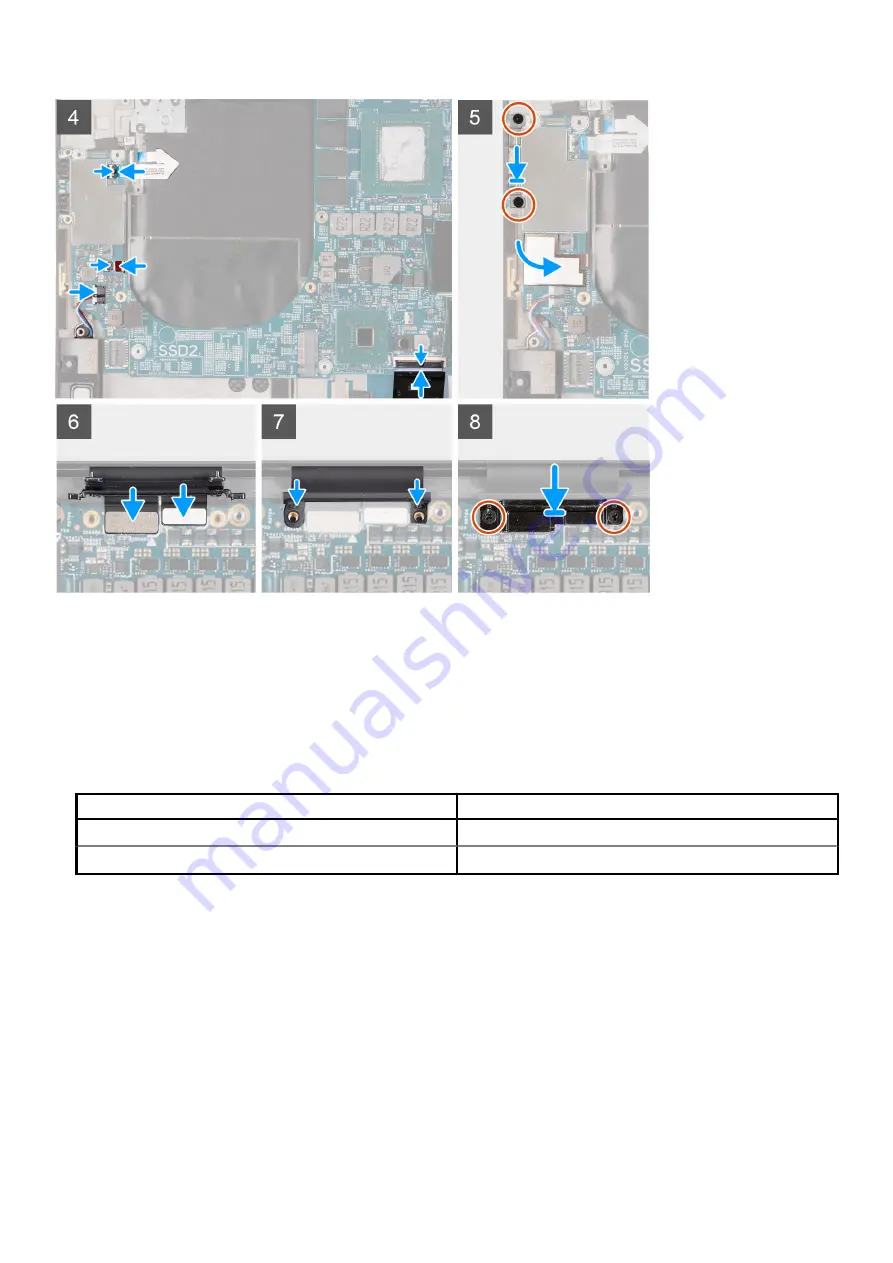
3. Connect the right antenna cable (applicable only to computers shipped with active antenna) to the system board and close the latch
to secure the right antenna cable to the system board.
4. Connect the antenna cables to the wireless card.
The following table provides the antenna-cable color scheme for the wireless card that is supported by your computer.
Table 2. Antenna-cable color scheme
Connectors on the wireless card
Antenna-cable color
Main (white triangle)
White
Auxiliary (black triangle)
Black
5. Connect the right speaker cable to the system board and close the latch to secure the cable to the system board.
6. Replace the two screws (M2x4) that secure the power-button bracket to the palm-rest and keyboard assembly.
7. Adhere the Mylar that secures the right antenna cable and the antenna cables to the system board.
8. Replace the screw (M2x4) that secures the wireless-card bracket to the system board.
9. Connect the power-button cable to the system board and close the latch to secure the cable to the system board.
10. Connect the left antenna cable (applicable only to computers shipped with active antenna) to the system board and close the latch to
secure the cable to the system board.
11. Connect the left speaker cable to the system board and close the latch to secure the cable to the system board.
12. Connect the keyboard cable to the system board and close the latch to secure the cable to the system board.
13. Replace the two screws (M2x4) that secure the USB Type-C port bracket to the palm-rest and keyboard assembly.
14. Adhere the Mylar that secures the power-button cable and the left antenna cable (applicable only to computers shipped with active
antenna) to the system board.
15. Connect the display cable and the camera cable to the system board.
16. Align the screw holes on the display-cable bracket with the screw holes on the system board.
Removing and installing components
45
Summary of Contents for XPS 17 9700
Page 1: ...XPS 17 9700 Service Manual Regulatory Model P92F Regulatory Type P92F001 May 2020 Rev A00 ...
Page 11: ...Removing and installing components 11 ...
Page 13: ...Removing and installing components 13 ...
Page 36: ...36 Removing and installing components ...
Page 38: ...38 Removing and installing components ...


