84
Top Cover
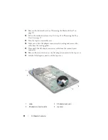
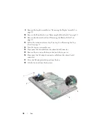
Replacing the Top Cover
1
Follow the instructions in "Before You Begin" on page 9.
2
Replace the speakers (see "Replacing the Speaker" on page 131).
3
Replace the system board (see "Replacing the System Board" on page 125)
4
Replace the TV antenna connector (see "Replacing the TV Antenna
5
Replace the I/O board (see "Replacing the I/O Board" on page 113).
6
Replace the processor module (see "Replacing the Processor Module" on
7
Replace the heat sink (see "Replacing the Heat Sink" on page 103).
8
Replace the fan (see "Replacing the Fan" on page 97).
9
Replace the AC-adapter connector (see "Replacing the AC-Adapter
10
Replace the USB board (see "Replacing the USB Board" on page 120).
11
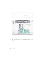
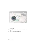
Route the subwoofer cable through the slot on the top cover.
12
Connect the subwoofer cable to the system-board connector.
13
Align the tabs on the top cover with the slots on the base cover and snap
the top-cover assembly onto the base cover.
14
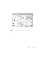
Replace the ten screws that secure the top-cover assembly to the base
cover.
15
Turn the computer over and replace the ten screws that secure the
top-cover assembly to the base cover.
16
Replace the Bluetooth-card (see "Replacing the Bluetooth Card" on
17
Replace the Mini-Card(s) (see "Replacing the Mini-Card(s)" on page 23).
18
Replace the display assembly (see "Replacing the Display Assembly" on
19
Replace the keyboard (see "Replacing the Keyboard" on page 45).
20
Replace the palm-rest assembly (see "Replacing the Palm-Rest Assembly"
21
Replace the optical drive (see "Replacing the Optical Drive" on page 34).
Summary of Contents for XPS L701X
Page 1: ...Dell XPS L701X Service Manual Regulatory model P09E series Regulatory type P09E001 ...
Page 12: ...12 Before You Begin ...
Page 26: ...26 Wireless Mini Card s ...
Page 32: ...32 Hard Drive s ...
Page 35: ...Optical Drive 35 ...
Page 36: ...36 Optical Drive ...
Page 42: ...42 Palm Rest Assembly ...
Page 50: ...50 Power Button Board ...
Page 54: ...54 Coin Cell Battery ...
Page 58: ...58 Internal Card With Bluetooth Wireless Technology ...
Page 72: ...72 Display ...
Page 78: ...78 Camera Module ...
Page 81: ...Top Cover 81 16 Disconnect the subwoofer cable from the system board connector ...
Page 86: ...86 Top Cover ...
Page 90: ...90 Subwoofer ...
Page 94: ...94 AC Adapter Connector ...
Page 98: ...98 Fan ...
Page 99: ...Fan 99 ...
Page 100: ...100 Fan ...
Page 104: ...104 Heat Sink ...
Page 105: ...Heat Sink 105 ...
Page 106: ...106 Heat Sink ...
Page 122: ...122 USB Board ...
Page 128: ...128 System Board ...

