• The ACL configuration information that the ACL logging application receives from the ACL manager
causes the allocation and clearance of the match rule number. A unique match rule number is
created for the combination of each ACL entry, sequence number, and interface parameters.
• A separate set of match indices is preserved by the ACL logging application for the permit and deny
actions. Depending on the action of an ACL entry, the corresponding match index is allocated from
the particular set that is maintained for permit and deny actions.
• A maximum of 125 ACL entries with permit action can be logged. A maximum of 126 ACL entries with
deny action can be logged.
• For virtual ACL entries, the same match rule number is reused. Similarly, when an ACL entry is deleted
that was previously enabled for ACL logging, the match rule number used by it is released back to the
pool or available set of match indices so that it can be reused for subsequent allocations.
• If you enabled the count of packets for the ACL entry for which you configured logging, and if the
logging is deactivated in a specific interval owing to the threshold having exceeded, the count of
packets that exceeded the logging threshold value during that interval is logged when the subsequent
log record (in the next interval) is generated for that ACL entry.
• When you delete an ACL entry, the logging settings associated with it are also removed.
• ACL logging is supported for standard and extended IPv4 ACLs, IPv6 ACLs, and standard and extended
MAC ACLs.
• For ACL entries applied on port-channel interfaces, one match index for every member interface of
the port-channel interface is assigned. Therefore, the total available match indices of 251 are split (125
match indices for permit action and 126 match indices for the deny action).
• You can configure ACL logging only on ACLs that are applied to ingress interfaces; you cannot enable
logging for ACLs on egress interfaces.
• The total available match rule indices is 255 with four match indices used by other modules, leaving
251 indices available for ACL logging.
Configuring ACL Logging
This functionality is supported on the Z9000 platform.
To configure the maximum number of ACL log messages to be generated and the frequency at which
these messages must be generated, perform the following steps:
NOTE: This example describes the configuration of ACL logging for standard IP access lists. You can
enable the logging capability for standard and extended IPv4 ACLs, IPv6 ACLs, and standard and
extended MAC ACLs.
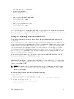
1.
Specify the maximum number of ACL logs or the threshold that can be generated by using the
threshold-in-msgs
count
option with the seq, permit, or deny commands. Upon exceeding the
specified maximum limit, the generation of ACL logs is terminated. You can enter a threshold in the
range of 1-100. By default, 10 ACL logs are generated if you do not specify the threshold explicitly.
CONFIG-STD-NACL mode
seq
sequence-number
{deny | permit} {source [mask] | any | host
ip-address
}
[log [threshold-in-msgs
count
] ]
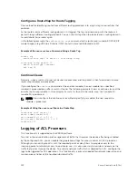
2.
Specify the interval in minutes at which ACL logs must be generated. You can enter an interval in the
range of 1-10 minutes. The default frequency at which ACL logs are generated is 5 minutes. If ACL
logging is stopped because the configured threshold has exceeded, it is re-enabled after the logging
interval period elapses. ACL logging is supported for standard and extended IPv4 ACLs, IPv6 ACLs,
and standard and extended MAC ACLs. Configure ACL logging only on ACLs that are applied to
ingress interfaces; you cannot enable logging for ACLs that are associated with egress interfaces.
124
Access Control Lists (ACLs)
Summary of Contents for Z9000
Page 1: ...Dell Configuration Guide for the Z9000 System 9 7 0 0 ...
Page 80: ...grub reboot 80 Management ...
Page 128: ... 0 Te 1 1 Te 1 2 rx Flow N A N A 128 Access Control Lists ACLs ...
Page 491: ...Figure 70 Configuring OSPF and BGP for MSDP Multicast Source Discovery Protocol MSDP 491 ...
Page 496: ...Figure 73 MSDP Default Peer Scenario 1 496 Multicast Source Discovery Protocol MSDP ...
Page 497: ...Figure 74 MSDP Default Peer Scenario 2 Multicast Source Discovery Protocol MSDP 497 ...
Page 498: ...Figure 75 MSDP Default Peer Scenario 3 498 Multicast Source Discovery Protocol MSDP ...
Page 760: ...Figure 100 Single and Double Tag TPID Match 760 Service Provider Bridging ...
Page 761: ...Figure 101 Single and Double Tag First byte TPID Match Service Provider Bridging 761 ...


