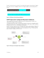
UDP Helper with Broadcast-All Addresses
When the destination IP address of an incoming packet is the IP broadcast address, Dell Networking OS
rewrites the address to match the configured broadcast address.
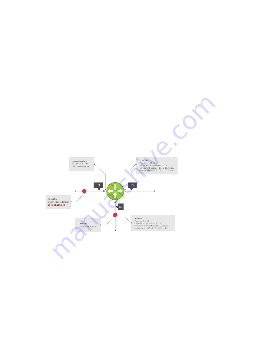
In the following illustration:
1.
Packet 1 is dropped at ingress if you did not configure UDP helper address.
2.
If you enable UDP helper (using the
ip udp-helper udp-port
command), and the UDP
destination port of the packet matches the UDP port configured, the system changes the destination
address to the configured broadcast 1.1.255.255 and routes the packet to VLANs 100 and 101. If you
do not configure an IP broadcast address (using the
ip udp-broadcast-address
command) on
VLANs 100 or 101, the packet is forwarded using the original destination IP address 255.255.255.255.
Packet 2, sent from a host on VLAN 101 has a broadcast MAC address and IP address. In this case:
1.
It is flooded on VLAN 101 without changing the destination address because the forwarding process
is Layer 2.
2.
If you enabled UDP helper, the system changes the destination IP address to the configured
broadcast address 1.1.255.255 and forwards the packet to VLAN 100.
3.
Packet 2 is also forwarded to the ingress interface with an unchanged destination address because it
does not have broadcast address configured.
Figure 38. UDP Helper with Broadcast-All Addresses
UDP Helper with Subnet Broadcast Addresses
When the destination IP address of an incoming packet matches the subnet broadcast address of any
interface, the system changes the address to the configured broadcast address and sends it to matching
interface.
In the following illustration, Packet 1 has the destination IP address 1.1.1.255, which matches the subnet
broadcast address of VLAN 101. If you configured UDP helper and the packet matches the specified UDP
port, the system changes the address to the configured IP broadcast address and floods the packet on
VLAN 101.
376
IPv4 Routing
Summary of Contents for Z9000
Page 1: ...Dell Configuration Guide for the Z9000 System 9 7 0 0 ...
Page 80: ...grub reboot 80 Management ...
Page 128: ... 0 Te 1 1 Te 1 2 rx Flow N A N A 128 Access Control Lists ACLs ...
Page 491: ...Figure 70 Configuring OSPF and BGP for MSDP Multicast Source Discovery Protocol MSDP 491 ...
Page 496: ...Figure 73 MSDP Default Peer Scenario 1 496 Multicast Source Discovery Protocol MSDP ...
Page 497: ...Figure 74 MSDP Default Peer Scenario 2 Multicast Source Discovery Protocol MSDP 497 ...
Page 498: ...Figure 75 MSDP Default Peer Scenario 3 498 Multicast Source Discovery Protocol MSDP ...
Page 760: ...Figure 100 Single and Double Tag TPID Match 760 Service Provider Bridging ...
Page 761: ...Figure 101 Single and Double Tag First byte TPID Match Service Provider Bridging 761 ...


