3
Getting Started
This chapter describes how you start configuring your system.
When you power up the chassis, the system performs a power-on self test (POST) during which the line
card status light emitting diodes (LEDs) blink green. The system then loads the Dell Networking Operating
System (OS). Boot messages scroll up the terminal window during this process. No user interaction is
required if the boot process proceeds without interruption.
When the boot process completes, the RPM and line card status LEDs remain online (green) and the
console monitor displays the EXEC mode prompt.
For details about using the command line interface (CLI), refer to the
section in the
chapter.
Console Access
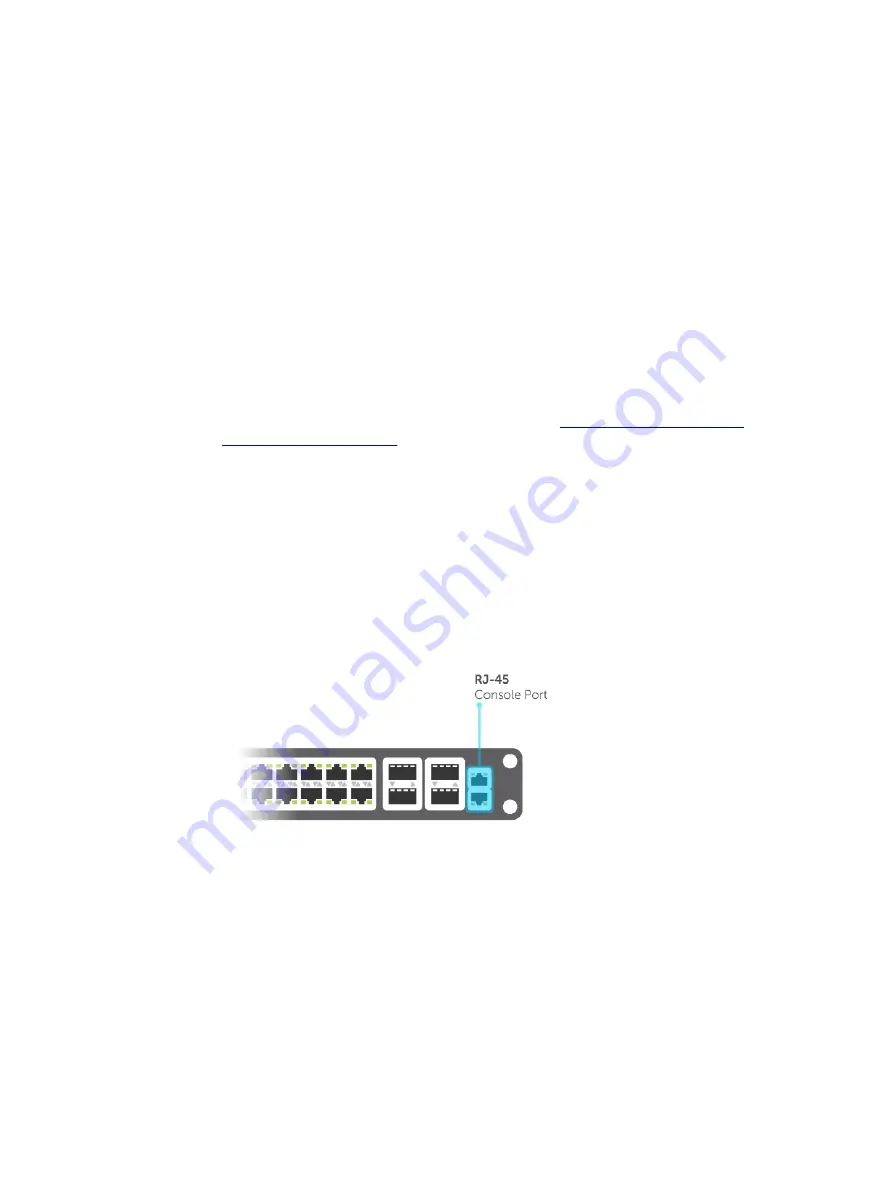
The Z9000 has a primary management (Ethernet) port and an RJ-45/RS-232 console port.
Serial Console
The RJ-45/RS-232 console port is labeled on the chassis. It is in the upper right-hand side, as you face
the I/O side of the chassis.
Figure 1. RJ-45 Console Port
1.
RJ-45 Console Port
Getting Started
43
Summary of Contents for Z9000
Page 1: ...Dell Configuration Guide for the Z9000 System 9 7 0 0 ...
Page 80: ...grub reboot 80 Management ...
Page 128: ... 0 Te 1 1 Te 1 2 rx Flow N A N A 128 Access Control Lists ACLs ...
Page 491: ...Figure 70 Configuring OSPF and BGP for MSDP Multicast Source Discovery Protocol MSDP 491 ...
Page 496: ...Figure 73 MSDP Default Peer Scenario 1 496 Multicast Source Discovery Protocol MSDP ...
Page 497: ...Figure 74 MSDP Default Peer Scenario 2 Multicast Source Discovery Protocol MSDP 497 ...
Page 498: ...Figure 75 MSDP Default Peer Scenario 3 498 Multicast Source Discovery Protocol MSDP ...
Page 760: ...Figure 100 Single and Double Tag TPID Match 760 Service Provider Bridging ...
Page 761: ...Figure 101 Single and Double Tag First byte TPID Match Service Provider Bridging 761 ...


