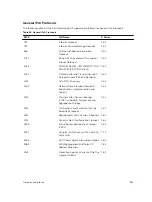
Internal Unit
Port Number
User Ports
from 0 to 31
on Unit 0
User Ports
from 32 to
63 on Unit 1
User Ports
from 64 to
95 on Unit 2
User Ports
from 96 to
127 on Unit 3
No User
Ports on Unit
4
No User
Ports on Unit
5
38
Internal
Internal
Internal
Internal
Internal
Internal
39
Internal
Internal
Internal
Internal
Internal
Internal
40
Internal
Internal
Internal
Internal
Internal
Internal
41
Internal
Internal
Internal
Internal
Internal
Internal
Environmental Monitoring
The Z9000 components use environmental monitoring hardware to detect transmit power readings,
receive power readings, and temperature updates.
To receive periodic power updates, enable the
enable optic-info-update interval
command.
The output in the following example displays the environment status of the RPM.
Example of the
show interfaces transceiver
Command
Dell#show interfaces
-- RPM Environment Status --
Slot Status Temp Voltage
----------------------------
0 active 33C ok
1 not present
Recognize an Over-Temperature Condition
An overtemperature condition occurs, for one of two reasons: the card genuinely is too hot or a sensor
has malfunctioned.
To discover the cause, inspect cards near the one reporting the condition.
• If directly adjacent cards are not normal temperature, suspect a genuine overheating condition.
• If directly adjacent cards are normal temperature, suspect a faulty sensor.
When the system detects a genuine over-temperature condition, it powers off the card. To recognize this
condition, look for the system messages shown in the following example.
Dell#show alarms threshold
-- Temperature Limits (deg C) --
-------------------------------------------------
Minor Minor Off Major Major Off Shutdown
Linecard 75 70 80 77 85
RPM 65 60 75 70 80
Dell#
Z-Series Debugging and Diagnostics
943
Summary of Contents for Z9000
Page 1: ...Dell Configuration Guide for the Z9000 System 9 7 0 0 ...
Page 80: ...grub reboot 80 Management ...
Page 128: ... 0 Te 1 1 Te 1 2 rx Flow N A N A 128 Access Control Lists ACLs ...
Page 491: ...Figure 70 Configuring OSPF and BGP for MSDP Multicast Source Discovery Protocol MSDP 491 ...
Page 496: ...Figure 73 MSDP Default Peer Scenario 1 496 Multicast Source Discovery Protocol MSDP ...
Page 497: ...Figure 74 MSDP Default Peer Scenario 2 Multicast Source Discovery Protocol MSDP 497 ...
Page 498: ...Figure 75 MSDP Default Peer Scenario 3 498 Multicast Source Discovery Protocol MSDP ...
Page 760: ...Figure 100 Single and Double Tag TPID Match 760 Service Provider Bridging ...
Page 761: ...Figure 101 Single and Double Tag First byte TPID Match Service Provider Bridging 761 ...


