7
Access Control List (ACL) VLAN Groups
and Content Addressable Memory (CAM)
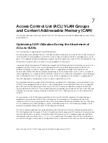
This chapter describes the access control list (ACL) VLAN group and content addressable memory (CAM)
enhancements.
Optimizing CAM Utilization During the Attachment of
ACLs to VLANs
This functionality is supported on the Z9000 platform.
You can enable and configure the ACL CAM optimization functionality to minimize the number of entries
in CAM while ACLs are applied on a VLAN or a set of VLANs, and also while ACLs are applied on a set of
ports. This capability enables the effective usage of the CAM space when Layer 3 ACLs are applied to a set
of VLANs and when Layer 2 or Layer 3 ACLs are applied on a set of ports.
In releases of Dell Networking OS that do not support the CAM optimization functionality, when an ACL is
applied on a VLAN, the ACL rules are configured with the rule-specific parameters and the VLAN as
additional attributes in the ACL region. When the ACL is applied on multiple VLAN interfaces, the
consumption of the CAM space increases proportionally. For example, when an ACL with ‘n’ number of
rules is applied on ‘m’ number of VLAN interfaces, a total of n*m entries are configured in the CAM region
that is allocated for ACLs. Similarly, when an L2 or L3 ACL is applied on a set of ports, a large portion of
the CAM space gets used because a port is saved as a parameter in CAM.
To avoid excessive consumption of the CAM space, configure ACL VLAN groups, which combine all the
VLANs that are applied with the same ACL, into a single group. A class identifier (Class ID) is assigned for
each of the ACLs attached to the VLAN and this Class ID is used as an identifier or locator in the CAM
space instead of the VLAN ID. This method of processing reduces the number of entries in the CAM area
significantly and saves memory space by using the class ID as a filtering criterion in CAM instead of the
VLAN ID.
You can create an ACL VLAN group and attach the ACL with the VLAN members. The optimization is
applicable only when you create an ACL VLAN group. If you apply an ACL separately on the VLAN
interface, each ACL has a mapping with the VLAN and increased CAM space utilization occurs. Attaching
an ACL individually to VLAN interfaces is similar to the behavior of ACL-VLAN mapping storage in CAM
prior to the implementation of the ACL VLAN group functionality.
The ACL manager application on router processor (RP1) contains all the state information about all the
ACL VLAN groups that are present. The ACL handler on control processor (CP) and the ACL agent on line
cards do not contain any stateful information about the group. The ACL manager application performs
the validation after you enter the
acl-vlan-group
command. If the command is valid, it is processed
and sent to the agent, if required. If a configuration error is found or if the maximum limit has exceeded
Access Control List (ACL) VLAN Groups and Content Addressable Memory (CAM)
129
Summary of Contents for Z9000
Page 1: ...Dell Configuration Guide for the Z9000 System 9 7 0 0 ...
Page 80: ...grub reboot 80 Management ...
Page 128: ... 0 Te 1 1 Te 1 2 rx Flow N A N A 128 Access Control Lists ACLs ...
Page 491: ...Figure 70 Configuring OSPF and BGP for MSDP Multicast Source Discovery Protocol MSDP 491 ...
Page 496: ...Figure 73 MSDP Default Peer Scenario 1 496 Multicast Source Discovery Protocol MSDP ...
Page 497: ...Figure 74 MSDP Default Peer Scenario 2 Multicast Source Discovery Protocol MSDP 497 ...
Page 498: ...Figure 75 MSDP Default Peer Scenario 3 498 Multicast Source Discovery Protocol MSDP ...
Page 760: ...Figure 100 Single and Double Tag TPID Match 760 Service Provider Bridging ...
Page 761: ...Figure 101 Single and Double Tag First byte TPID Match Service Provider Bridging 761 ...


