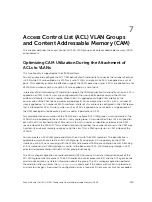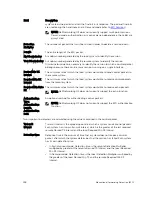
• The maximum number of VLANs that you can configure as a member of ACL VLAN groups is limited
to 512 on the Z9000 switch if two slices are allocated. If only one virtual flow processing slice is
allocated, the maximum number of VLANs that you can configure as a member of an ACL VLAN
group is 256 for the Z9000 switch.
• Port ACL optimization is applicable only for ACLs that are applied without the VLAN range.
• You cannot view the statistical details of ACL rules per VLAN and per interface if you enable the ACL
VLAN group capability. You can view the counters per ACL only using the
show ip accounting
access list
command.
• Within a port, you can apply Layer 2 ACLs on a VLAN or a set of VLANs. In this case, CAM optimization
is not applied.
• To enable optimization of CAM space for Layer 2 or Layer 3 ACLs that are applied to ports, the port
number is removed as a qualifier for ACL application on ports, and port bits are used. When you apply
the same ACL to a set of ports, the port bitmap is set when the ACL flow processor (FP) entry is added.
When you remove the ACL from a port, the port bitmap is removed.
• If you do not attach an ACL to any of the ports, the FP entries are deleted. Similarly, when the same
ACL is applied on a set of ports, only one set of entries is installed in the FP, thereby effectively saving
CAM space. The optimization is enabled only if you specify the optimized option with the
ip
access-group
command. This option is not valid for VLAN and LAG interfaces.
Configuring ACL VLAN Groups and Configuring FP Blocks
for VLAN Parameters
This section describes how to optimize the utilization of CAM blocks by configuring ACL VLAN groups
that you can attach to VLAN interfaces and also how to configure FP blocks for different VLAN
operations.
Configuring ACL VLAN Groups
You can create an ACL VLAN group and attach the ACL with the VLAN members. The optimization is
applicable only when you create an ACL VLAN group. If you apply an ACL separately on the VLAN
interface, each ACL has a mapping with the VLAN and increases the CAM space utilization. Attaching an
ACL individually to VLAN interfaces is similar to the behavior of ACL-VLAN mapping storage in CAM prior
to the implementation of the ACL VLAN group functionality.
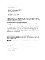
1.
Create an ACL VLAN group
CONFIGURATION mode
acl-vlan-group {
group name
}
You can have up to eight different ACL VLAN groups at any given time.
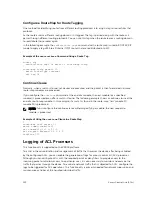
2.
Add a description to the ACL VLAN group.
CONFIGURATION (conf-acl-vl-grp) mode
description
description
3.
Apply an egress IP ACL to the ACL VLAN group.
CONFIGURATION (conf-acl-vl-grp) mode
ip access-group {
group name
} out implicit-permit
4.
Add VLAN member(s) to an ACL VLAN group.
Access Control List (ACL) VLAN Groups and Content Addressable Memory (CAM)
131
Summary of Contents for Z9000
Page 1: ...Dell Configuration Guide for the Z9000 System 9 7 0 0 ...
Page 80: ...grub reboot 80 Management ...
Page 128: ... 0 Te 1 1 Te 1 2 rx Flow N A N A 128 Access Control Lists ACLs ...
Page 491: ...Figure 70 Configuring OSPF and BGP for MSDP Multicast Source Discovery Protocol MSDP 491 ...
Page 496: ...Figure 73 MSDP Default Peer Scenario 1 496 Multicast Source Discovery Protocol MSDP ...
Page 497: ...Figure 74 MSDP Default Peer Scenario 2 Multicast Source Discovery Protocol MSDP 497 ...
Page 498: ...Figure 75 MSDP Default Peer Scenario 3 498 Multicast Source Discovery Protocol MSDP ...
Page 760: ...Figure 100 Single and Double Tag TPID Match 760 Service Provider Bridging ...
Page 761: ...Figure 101 Single and Double Tag First byte TPID Match Service Provider Bridging 761 ...


