background image


-  - 

6

5.6 FCC 

 
This device complies with Part 15 of the FCC Rules. Operation is subject to the following two 
conditions:(1) this device may not cause harmful interference, and (2) this device must accept any 
interference received, including interference that may cause undesired operation. 


This equipment has been tested and found to comply with the limits for a Class B digital device, 

pursuant to Part 15 of the FCC Rules. These limits are designed to provide reasonable protection against 

harmful interference in a residential installation. This equipment generates, uses and can radiate radio 

frequency energy and, if not installed and used in accordance with the instructions, may cause harmful 

interference to radio communications. However, there is no guarantee that interference will not occur in 

a particular installation. If this equipment does cause harmful interference to radio or television 

reception, which can be determined by turning the equipment off and on, the user is encouraged to try to 

correct the interference by one or more of the following measures: 

--Reorient or relocate the receiving antenna. 

--Increase the separation between the equipment and receiver. 

--Connect the equipment into an outlet on a circuit different from that to which the receiver is 

connected. 

--Consult the dealer or an experienced radio/TV technician for help. 
 
Shielded interface cables must be used in order to comply with emission limits. 


Changes or modifications not expressly approved by the party responsible for compliance could void the 

user‘s authority to operate the equipment. 


CAUTION 

Any changes or modifications not expressly approved by the grantee of this device could void the user’s 

authority to operate the equipment. 


FCC RF Radiation Exposure Statement 

This equipment complies with FCC RF radiation exposure limits set forth for an uncontrolled 

environment. This equipment should be installed and operated with a minimum distance of 20cm 

between the radiator and your body. 


Summary of Contents for Earthmate PowerPack

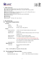
Page 1: ...DELORME PowerPack for Earthmate GPS with Bluetooth GPS 9822 Version 1 2 09 September 2003 All Rights Reserved ...

Page 2: ...ISTICS 2 2 4 CERTIFICATION 2 3 ACCESSORIES 2 3 1 POWER 2 3 2 CABLES OPTIONAL 2 4 OPERATION 3 4 1 HARDWARE DESCRIPTION 3 4 2 TURN ON OFF 3 4 3 CHARGING 4 4 4 BLUETOOTH COMMUNICATION 4 4 6 PIN CODE 4 5 NOTICES 5 5 1 GLOBAL POSITIONING SYSTEM 5 5 2 AIRCRAFT AND HOSPITALS 5 5 3 HEAT REFLECTIVE SHIELDS 5 5 4 IMPORTANT 5 5 5 BATTERY 5 5 6 FCC 6 ...

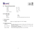
Page 3: ...nal Power 3 3VDC 10 from internal Lithium Ion battery pack Charging Power 5VDC 10 Battery Source Rechargeable 1200mAh Lithium Ion battery with 5V DC input charging circuit Battery Charging Full charge 2 5 hours by 650mA adapter Backup Power 3 3V internal onboard rechargeable backup battery Operational Current 70 80mA with BT function but not include Earthmate GPS 0 10 mA without BT function and no...

Page 4: ...C ID 3 Accessories 3 1 Power Adapter Adapter is for charging Supports 110V 220V Multiple 3 2 Cables Optional USB cable This cable switches C25 connector to USB connector The GPS data can be transmitted by USB port RS232 DB9 cable This cable switches C25 connector to RS232 DB9 connector The GPS data can be transmitted by UART port Cables for PDA These cables can support some PDAs to receive GPS dat...

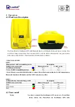
Page 5: ...ription LED1 Color and Action Bluetooth Active UART Active Blue Bluetooth status Yes No Yellow UART transmitting status No Yes Note When you use RS232 DB9 cable to connect PowerPack and enable the UART transmission Bluetooth function will disable and the LED 1 only shows yellow LED2 Lithium Battery Status Charge LED Description LED2 Color and Action Battery Charged Low Powered Dark No No Green Sol...

Page 6: ...indicator will switch off 4 4 Bluetooth Communication Waiting to connect The right LED LED 1 indicator will flash if there is no communication between the receiver and another device Connected The right LED LED 1 indicator will turn to continuous lighting when the receiver is connected through the wireless link with another device 4 6 PIN CODE The PIN code means Personal Identification Number for ...

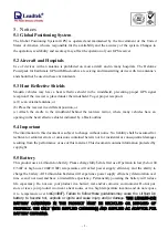
Page 7: ...tion in this document is subject to change without notice No liability shall be assumed for technical or editorial errors or omissions contained herein nor for incidental or consequential damages resulting from the performance or use of this material This document contains information protected by copyright 5 5 Battery This product uses a Lithium Ion battery Please charge fully before first use Op...

Page 8: ...levision reception which can be determined by turning the equipment off and on the user is encouraged to try to correct the interference by one or more of the following measures Reorient or relocate the receiving antenna Increase the separation between the equipment and receiver Connect the equipment into an outlet on a circuit different from that to which the receiver is connected Consult the dea...

Reviews: