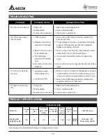
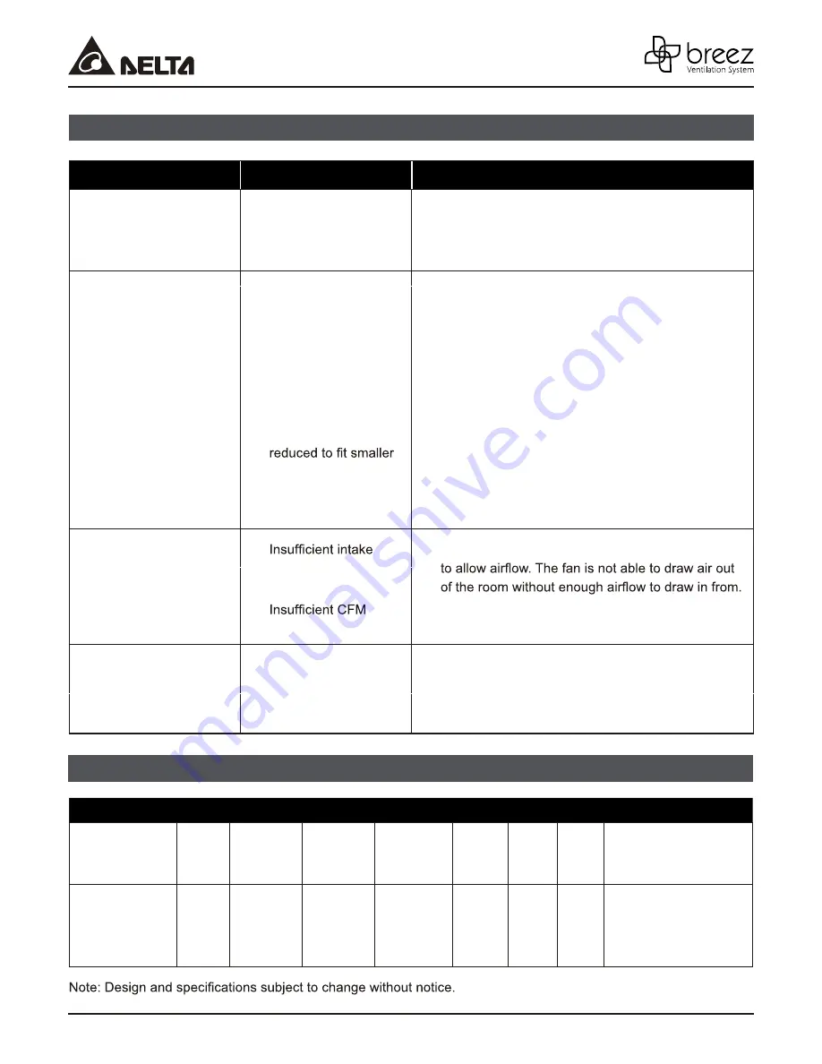
background image

10

 TROUBLESHOOTING

PROBLEM

POSSIBLE CAUSE

CORRECTIVE ACTION

The fan is not turning on

1. Power off
2. Faulty switch
3. Faulty wire connection

1. Make sure power supply is on.
2. Test or replace switch.
3. Check wire in switch box.

The fan seems louder 
than it should

1.


CFM too great


2.   Damper not working 

properly or damaged


3.   Bend in duct too close 

to fan discharge

4.   Fan discharge 

duct

5.   Fan body not securely 

attached

1.


Be sure the CFM rating on the fan matches the 
size of your room.

2.   Check damper to ensure it is opening and closing 

properly. If the damper has become damaged, 
please call Customer Service.

3.   Be sure you do not have any sharp bends in duct 

closer than 18 in. to the fan discharge.

4.   Use recommended size ducting to reduce fan 

noise.


5.   Be sure the fan is securely attached to your ceiling 

joists.

The fan is not clearing 
the room

1.   

airfow within room


2.   

1.   Be sure a door or window is slightly ajar or opened 

2.   Be sure the CFM rating on the fan matches the 

requirements for your room size.

The light is not turning 
ON

1. Power off
2. Faulty switch
3. Faulty wire connection

1. Make sure power supply is on.
2. Test or replace switch.
3. Check wire in switch box.

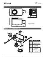
 PRODUCT SPECIFICATIONS

SPECIFICATIONS

Model No.

Voltage

(V)

Frequency 

(Hz)


Note

LED light spec

80LED-REC/

VFB080F4LED1

120

60

P

Power @ 

0.1”S  (W)

14.5

P

Air Flow 

@ 0.1”S

(CFM)

80

Weight 

(lb.)

8.8

Max.

Current 

(amps)

0.34

Single 

Speed

LED Light: 13W

850Lumens, 3000K


Summary of Contents for 80LED-REC

Page 1: ... 11 11 Warranty 12 VENTILATION FAN LED LIGHT MODELS 80LED REC VFB080F4LED1 Wiring Diagram 5 Product Specifications 10 Product Exploded Drawing MFG Model VFB080F4LED1 READ AND SAVE THESE INSTRUCTIONS Address 46101 Fremont Boulevard Fremont CA 94538 US Toll Free Number 1 888 979 9889 Technical Support 1 877 685 4384 Customer Sales Support www deltabreez com ...

Page 2: ...S PART DESCRIPTION QTY Fan Body 1 LED Module 1 Suspension bracket Ⅰ 13 318 5mm 2 Suspension bracket Ⅱ 13 318 5mm 2 1 2 3 4 A B HARDWARE CONTENTS Images are to scale X 8 X 4 Long Wood Screw 4 x 25mm Short Screw 8 32x1 4 ...

Page 3: ... and safety standards such as those published by the National Fire Protection Association NFPA and the American Society for Heating Refrigeration and Air Conditioning Engineers ASHRAE and local code authorities 5 When cutting or drilling into the ceiling do not damage electrical wiring and other hidden utilities 6 Ducted ventilating fans must always be vented to the outdoors GENERAL SAFETY INFORMA...

Page 4: ...allation of your bath fan are not all included However most are available at your local home improvement or hardware store Properly insulate around the fan to minimize building heat loss and gain The ducting from this fan to the outside of the building has a strong effect on the airflow noise and energy use of the fan Use the shortest straightest duct routing possible for best performance and avoi...

Page 5: ... ON BLACK ON OFF SWITCH purchase separately SWITCH BOX 120 VAC LINE IN WHITE GROUND bare FAN WIRING PLATE RED Dual Switch Control With dual switches the fan and light can be controlled independently LIGHT BLACK ON OFF SWITCH purchase separately SWITCH BOX 120 VAC LINE IN WHITE GROUND bare FAN LIGHT WIRING PLATE RED Single Switch Control With a single switch all three features can be turned on and ...

Page 6: ...e bracket cover on the duct connector side and the back of the fan body Hardware Suspension Bracket II Suspension Bracket I Fan Body 1 3 2 16 406mm 19 2 487mm 24 609mm 2 1 A B X 8 X 4 2 Make sure there will be a gap 1 8 inches 3 2mm between bottom of fan body and ceiling 1 8 3 2mm GAP Joist Suspension Bracket Ceiling ...

Page 7: ...to the outside Secure it with duct tape not supplied or clamp not supplied to make the connection secure and air tight 6 Cut a 6 1 2 inches 165mm dia opening Joist Joist Circular duct a a 6 1 2 inches 165mm Dia Ceiling Ceiling hole 6 5 4 Joist Joist Fan Body 1 3 Install the suspension brackets to the joists with long wood screws and secure the suspension brackets to the fan body by using the short...

Page 8: ...the LED light connector into the fan body 8 Attach LED module by pinching mounting springs a and insert into the narrow rectangular slots in fan body 7 8 2 Slots 2 Springs LED light connector LED module Springs Rectangular slot a 2 a 2 ...

Page 9: ...merse resin parts in water over 140º Fahrenheit CARE AND MAINTENANCE 3 Remove dust and dirt from the fan body with a vacuum cleaner 4 Dampen cloth with dust detergent and wipe the fan body Then wipe dry with a clean cloth 5 Replace LED module back onto fan body 6 Turn on power source to operate fan again 1 2 3 4 5 2 Turn off power source Review all safety precautions 1 To remove LED module squeeze...

Page 10: ... 3 Be sure you do not have any sharp bends in duct closer than 18 in to the fan discharge 4 Use recommended size ducting to reduce fan noise 5 Be sure the fan is securely attached to your ceiling joists The fan is not clearing the room 1 airfow within room 2 1 Be sure a door or window is slightly ajar or opened 2 Be sure the CFM rating on the fan matches the requirements for your room size The lig...

Page 11: ...9 6 8 7 8 226 2 12 3 4 324 9 4 100 0 3 7 8 97 2 Dia 7 1 2 190 0 6 1 2 161 6 Dia Unit Inches mm 1 2 12 0 Duct connector Suspension bracket Fan motor LED module Junction box cover Junction box Power unit PART DESCRIPTION 1 2 3 4 5 6 7 1 2 3 5 4 2 6 7 ...

Page 12: ...oducts will be shipped by Delta Electronics F O B shipping point 3 Delta Electronics shall not be liable for any indirect incidental consequential punitive or special damages arising out of or in connection with products use or performance regardless of the form of action whether in contract tort including negligence strict product liability or otherwise 4 5 The warranty does not cover if user doe...

Reviews: