R
N
V
U
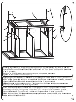
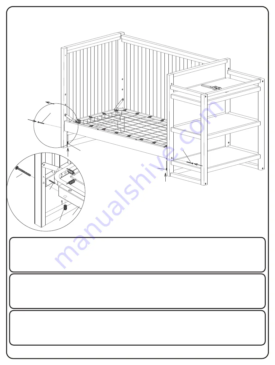
Attach (1) Stabilizer Bar (Part N) to the assembly from Section 4 Step 1 using (2) M4x30mm Metal Pins (Part U),
(2) 75 mm Bolts (Part R) and (2) Barrel Nuts (Part V). Tighten with the M4 Allen Wrench. Use the Flat Head
Screwdriver to hold the Barrel Nut in the proper alignment
N
R
R
V
V
PULL GENTLY
Tirez doucement
Tire con delicadeza
Fixez (1) barre stabilisatrice (pièce N) à l’assemblage de la section 4 étape 1 en utilisant (2)
broches métalliques M4X30mm (pièce U), (2) boulons 75mm (pièce R) et (2) écrous à portée
cylindrique (pièce V). Serrez à l’aide de la clé hexagonale m4. Utilisez le tourne vis à tête plate
pour tenir l’écrou à portée cylindrique dans son bon alignement.
Fije (1) barra estabilizadora (pieza N) al ensamblado de la sección 4 paso 1 utilizando (2) pasadores
de metal M4x30mm (pieza U), (2) pernos de 75 mm (pieza R) y (2) tuercas cilíndricas (pieza V).
Apriete con la llave Allen M4. Utilice el destornillador de cabeza plana para aguantar la tuerca
cilíndrica debidamente alineada.
Both Ends
Les deux extrémités
Ambos extremos
31

