background image

DeviceNet Network Scanner DVPDNET-SL


DVP-PLC Application Manual


9

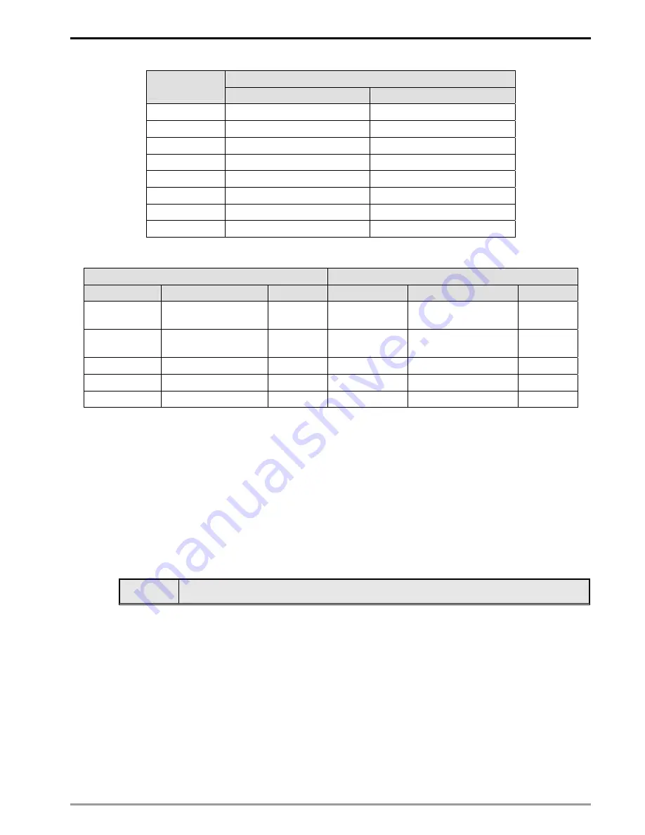
Mapped D registers 

DVPDNET-SL 

index 

Output mapping 

Input mapping 

1   

D6250 ~ D6497 

D6000 ~ D6247 

D6750 ~ D6997 

D6500 ~ D6747 

D7250 ~ D7497 

D7000 ~ D7247 

D7750 ~ D7997 

D7500 ~ D7747 

D8250 ~ D8497 

D8000 ~ D8247 

D8750 ~ D8997 

D8500 ~ D8747 

D9250 ~ D9497 

D9000 ~ D9247 

D9750 ~ D9997 

D9500 ~ D9747 

4.2 I/O 

Mapping 

Table 

Output mapping are 

Input mapping area 

D register 

Mapping area 

Data length

D register 

Mapping area 

Data length

D6250 ~ D6281 

Explicit message 
program request 

32 words 

D6000 ~ D6031

Explicit message 
program response 

32 words 

D6282 ~ D6285  Bit-strobe command 

4 words 

D6032 ~ D6035

Status of nodes in the 
scan list 

4 words 

D6286 Reserved 

1word 

D6036 

DVPDNET-SL status 

1 word 

D6287 ~ D6476  DeviceNet output data 

190 words

D6037 ~ D6226

DeviceNet input data 

190 words

D6477 ~ D6497  Reserved 

21 words 

D6227 ~ D6247

Reserved 

21 words 

Constructing DeviceNet Network 

In this section, we will present an application example, illustrating how to construct a DeviceNet network and 

the configuration of the network. Before constructing a network, you have to first know clearly what the network 

is for and start a preliminary planning for the data to be exchanged. The plan shall include the maximum 

communication distance, slaves to be used, total length of data to be exchanged and so on. These information 

will decide whether the network you construct is a reasonable one, or if it satisfies your needs, and even affect 

the later-on network sustainability and flexibility of network capacity upgrade.


5.1 

How to Construct a DeviceNet Network 

Target 

Using a remote digital I/O module to control RUN/STOP of VFD-B AC motor drive. 

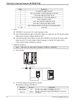
1. The connection 

Summary of Contents for DVPDNET-SL

Page 1: ...DVPDNET SL DeviceNet Network Scanner Application Manual ...

Page 2: ......

Page 3: ...hine and equipment In order not to damage it only qualified professional staff familiar with the structure and operation of DVPDNET SL can install operate wire and maintain it DO NOT connect input AC power supply to any of the I O terminals otherwise serious damage may occur Check all the wirings again before switching on the power and DO NOT touch any terminal when the power is switched on Make s...

Page 4: ...twork 9 5 2 How to Configure Network by DeviceNet Network Configuration Tool 10 5 3 DeviceNet Network Control 18 6 SENDING EXPLICIT MESSAGE FROM LADDER DIAGRAM 20 6 1 The Principle of Explicit Message Sending 20 6 2 Structure of Explicit Message 20 7 BIT STROBE COMMAND 26 7 1 Principle of Bit Strobe 26 8 DISPLAY OF NODE STATUS ON NETWORK 26 8 1 Display of Node Status in Scan List 26 8 2 Status of ...

Page 5: ...nctions of DVPDNET SL DVPDNET SL DeviceNet Network Scanner can be used both as a master or a slave in DeviceNet When being used as a master it supports the following functions z Client function of explicit message z All kinds of I O connections established between the slave polled bit strobed change of state and cyclic z As the connection interface between DeviceNetBuilder configuration software a...

Page 6: ...hen a slave device is configured into the scan list the software will automatically allocate a I O data exchange are of corresponding length to the slave from the mapping table The I O table is the data exchange interface between the PLC MPU and the slave device It corresponds the I O data in the D register of the MPU with the I O data in the slave After you configure the network download the conf...

Page 7: ...n I O 1KV Damped Oscillatory Wave Power Line 1KV Digital I O 1KV RS IEC 61131 2 IEC 61000 4 3 26MHz 1GHz 10V m Operation 0ºC 55ºC temperature 50 95 humidity pollution degree 2 Storage 25ºC 70ºC temperature 5 95 humidity Vibration shock resistance Standard IEC 61131 2 IEC 68 2 6 TEST Fc IEC 61131 2 IEC 68 2 27 TEST Ea Certificates IEC 61131 2 UL508 2 Product Profile Outline 2 1 Dimension 3 2 0 1 4 ...

Page 8: ...99 Invalid DeviceNet node address 9 1 6 4 5 0 0 9 1 3 2 7 8 2 5 6 4 3 7 8 Example If you need to set the node address of DVPDNET SL to 26 simply switch the corresponding switch of x101 to 2 and the corresponding switch of x100 to 6 Note z Please set up the node address when the power is switched off After the setup is completed re power DVPDNET SL z When DVPDNET SL is operating changing the settin...

Page 9: ...tal indicator provides the following two functions DVPDNET POWER MS NS 1 Displaying the node address and error messages of DVPDNET SL and error messages 2 Displaying the error message of slave 2 7 Extension Port The extension port is used on connecting DVPDNET SL to the left side extension port on DVP SV PLC MPU or to other extension modules connected to the left side of DVP SV 3 Basic Operation 3...

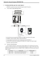
Page 10: ... connection port match the colors of the connection cables Make sure you connect the cable to the right PIN We recommend you also apply Delta s power module in the connection 4 Configuration 4 1 Corresponding Relation between DVPDNET SL and DVP SV After all DVPDNET SL are connected to DVP SV DVP SV will distribute data mapping areas to every DVPDNET SL DVPDNET DVP28SV RUN STOP DVPDNET DVPDNET DVPD...

Page 11: ...76 DeviceNet output data 190 words D6037 D6226 DeviceNet input data 190 words D6477 D6497 Reserved 21 words D6227 D6247 Reserved 21 words 5 Constructing DeviceNet Network In this section we will present an application example illustrating how to construct a DeviceNet network and the configuration of the network Before constructing a network you have to first know clearly what the network is for an...

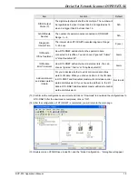
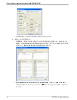
Page 12: ...ode 03 DeviceNet network configuration tool 2 Set up DVPDNET SL DNA01 and RTU DNET according to the table below Module Node address Baud rate DVPDNET SL 01 500 kbps IFD9502 02 500 kbps RTU DNET 03 500 kbps 5 2 How to Configure Network by DeviceNet Network Configuration Tool 1 Configuration of DeviceNet slave 1 Open DeviceNetBuilder software as below 2 Select Setup Communication Setting System Chan...

Page 13: ...rt on the PC to be used to communicate with DVP SV COM1 Address Communication address of DVP SV 01 Baud rate Communication speed between the PC and DVP SV 9 600 bps Data Bits 7 Parity Even Parity Stop Bit Communication protocol between the PC and DVP SV 1 Mode Communication mode between the PC and DVP SV ASCII Click on OK and return to the main page 4 Select Network Online and the Select Communica...

Page 14: ...e PC and DVP SV is abnormal or there are other programs also using the COM port on the PC After the scan is completed the dialog box will tell you that the scan is completed and the icons and device names of all the nodes scanned on the network will be shown on the screen See the figure below in which the node address of DVPDNET SL is 01 7 Double click on RTU DNET node 02 and the Node Configuratio...

Page 15: ...iguration dialog box and you will then see RTU Configuration page 9 Click on Scan IO and the Warning dialog box will appear 10 Click on OK DeviceNetBuilder will then detect the special module connected to RTU DNET and the number of points in the DI DO module and display the information on RTU Configuration page ...

Page 16: ...2 bytes One input channel of the special module occupies 2 bytes 8 points of the digital input are counted as 1 byte N A Output IO Data Length The sum of the length of the control word of RTU DNET and the output data of the special module connected to it The control word of RTU DNET occupies 2 bytes One output channel of the special module occupies 2 bytes 8 points of the digital output are counte...

Page 17: ...dule Error Treatment How RTU DNET will react when it detects errors You can choose Ignored Alarm or Stop DeviceNet IO Alarm Add control word and status word to IO data For you to decide whether to add control word and status word to I O data When you choose not to do it the I O data in RTU DNET and DeviceNet master will not include control word and status word If you choose to add them in the I O ...

Page 18: ...the Scan Module Configuration dialog box will appear You can find the currently available nodes RTU DNET and VFD B Drives 230V 3HP in the list on the left side On the right side there is an empty Scan List 2 Move the slave devices on DeviceNet in the Available Nodes list on the left side to the Scan List on the right side Select a node and click on Follow the steps to move all the nodes to the sca...

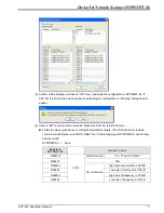
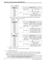
Page 19: ...Make sure DVP SV is in RUN mode Follow the steps given above to configure DeviceNet network If the I O data do not include control word and status word of RTU DNET the I O data mapping of DVPDNET SL and its slave devices will be DVPDNET SL slave Register in DVPDNET SL Devices in slave D6287H DI DO module Y0 Y7 on DVP 16SP D6287L N A D6288H High byte of command in VFD B D6288L Low byte of command i...

Page 20: ... in VFD B D6290L AC motor drive Low byte of frequency in VFD B Slave DVPDNET SL Register in DVPDNET SL Devices in slave D6037H High byte of status word in RTU DNET D6037L RTU DNET status word Low byte of status word in RTU DNET D6038H DI DO module X0 X7 on DVP 16SP D6038L N A D6039H Status of LED on VFD B D6039L Status of VFD B D6040H High byte of frequency in VFD B D6040L AC motor drive Low byte ...

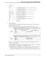
Page 21: ...3 12 11 10 9 8 7 6 5 4 3 2 1 0 D6037 X7 X6 X5 X4 X3 X2 X1 X0 N A D6038 Status of VFD B Status of LED on VFD B D6039 Frequency of VFD B D6040 Input data PLC device 15 14 13 12 11 10 9 8 7 6 5 4 3 2 1 0 D6287 Y7 Y6 Y5 Y4 Y3 Y2 Y1 Y0 N A D6288 Control word in VFD B D6289 Frequency in VFD B D6290 Output data When X0 On b8 of D6037 1 b8 of D6037 corresponds to M8 and therefore M8 On That is when X1 On ...

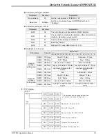
Page 22: ...request message to the target equipment The target equipment processes the request message and responds DVPDNET SL DVP SV MPU stores the response message from DVPDNET SL to D register One explicit message transmission is therefore completed 6 2 Structure of Explicit Message You can edit explicit messages in explicit request message editing area and explicit response message editing area See the ta...

Page 23: ... is counted as 1 byte The maximum data length is 58 bytes Errors will occur when the length is longer than 58 bytes Unit byte Port The communication port Fixed to 00Hex MAC ID The node address of the target equipment on DeviceNet Service Code The service code of the explicit message See the meanings of the codes in the table below Service Code Explanation 01Hex Read all attributes Get_Attribute_Al...

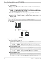
Page 24: ...L program we suggest you clear the request message editing area and response message editing area to 0 If the slava responds with standard error code and DVPDNET SL also consider the communication being successful The communication of explicit message is successful will indicate that the communication has been completed successfully 4 Application example I Target When M0 On read Class 1 Instance 1...

Page 25: ...x ReqID 01Hex Command 01Hex D6251 0005Hex Port 00Hex Size 05Hex D6252 0E02Hex Service Code 0EHex MAC ID 02Hex D6253 0001Hex High bye of Class ID 00Hex Low byte of Class ID 01Hex D6254 0001Hex High byte of Instance ID 00Hex Low byte of Instance ID 01Hex Request message editing area D6255 0001Hex N A Attribute ID 01Hex D6000 0101Hex ReqID 01Hex Status 01Hex D6001 0002Hex Port 00Hex Size 02Hex D6002 ...

Page 26: ...en the reading is successful the message responded from the target equipment will be stored in D6000 D6003 5 Application example II Target M1 On set 0x99 Instance 1 Attribute 2 of IFD9502 to 0004Hex 1 The connection 2 Compulsory settings and explanations on devices Compulsory settings in DVPDNET SL Parameter Set value Explanation Node address 00 Set the node address of DVPDNET SL to 00 Baud rate 5...
Page 27: ... D6255 0002Hex N A Attribute ID 02Hex Request message editing area D6256 0004Hex High byte of data 00Hex Low byte of data 04Hex D6000 0101Hex ReqID 01Hex Status 01Hex D6001 0002Hex Port 00Hex Size 02Hex D6002 9002Hex Service Code 90EHex MAC ID 02Hex Response message editing area D6003 0004Hex High byte of Service Data 00Hex Low byte of Service Data 04Hex 3 PLC program MOV H0101 D6250 M1002 ZRST D6...

Page 28: ...de 0 D6283 Node 31 Node 30 Node 29 Node 17 Node 16 D6284 Node 47 Node 46 Node 45 Node 33 Node 32 D6285 Node 63 Node 62 Node 61 Node 49 Node 48 When b0 of D6282 0 the node 0 equipment will be selected and it will need to respond with a message to the master When b0 and b1 of D6282 0 the node 0 and node 1 equipment will be selected and they will beed to respond with a message to the master b0 b1 b17...

Page 29: ...ndicator LED Explanation PLC device b15 b14 b13 b12 b11 b10 b9 b8 b7 b6 b5 b4 b3 b2 b1 b0 D6036 Status of DVPDNET SL 0 normal 1 initializing 2 error Error codes of DVPDNET SL See 9 5 9 LED Indicator Trouble shooting There are three LED indicators and one digital indicator on DVPDNET SL POWER LED displays if the power of DVPDNET SL is working normally NS LED and MS LED display the communication con...

Page 30: ...heck if the configuration is valid 2 Re power it If the error still exists send it back to the factory for repair 9 4 MS NS LED LED status NS LED MS LED Indication How to correct Off Off No power Make sure DVPDNET SL is powered Off Green light on Duplicate ID check has not completed Make sure at least 1 node or more are communicating in the network and the baud rate is the same as the setting in D...

Page 31: ... back to the factory for repair FA Invalid configuration data 1 Configure the network correctly and re download it to DVPDNET SL 2 Check if the node address of the slave in the scan list is the same as the node address of DVPDNET SL E0 Device key parameter does not match the scan list table Make sure that the device parameter in the scan list matches the desired key parameter including vendor ID p...

Page 32: ...DeviceNet Network Scanner DVPDNET SL DVP PLC Application Manual 30 MEMO ...

Reviews: