INSTALLATION
SM6000
13 / 21
DELTA ELEKTRONIKA B.V.
rev. Nov. 2020
4
INSTALLATION
Warning!
carefully read the chapter "Safety Instructions" in
this manual before connecting or operating the unit!
4.1
HUMIDITY & CONDENSATION
During normal operation, humidity will not harm the power
supply, provided the air is not aggressive. The heat normally
produced in the power supply will keep it dry.
Avoid condensation inside the power supply, to prevent
break-down. Condensation can occur during a period the
power supply has been switched off (or operating at no load)
and the ambient temperature is increasing. Always allow the
power supply to dry before switching it on again.
4.2
TEMPERATURE & COOLING
The storage temperature range is
–40 to +85 °C.
The operating temperature range at full load is
–20 to +50 °C.
This temperature range only holds when the air-intakes and
air-outlets are unobstructed and the temperature of the air-
intake is not higher than +50 °C.
When the power supply is mounted in a cabinet, please note
that the temperature of the air-intake should be kept low and
avoid a short circuit in the airflow i.e. the hot air leaving the
air-outlets entering the air-intakes again.
Please note: a lower temperature extends the lifetime of the
power supply.
4.3
19" RACK MOUNTING
On both sides in the rack, mount a proper support slide that
can hold the weight of the unit. It is advised to use a separate
slide for each unit.
After placing the unit on the slide, add all 4 screws to mount
the front panel of the power supply to the vertical rack posts.
Use proper screws intended for keeping equipment of this
weight in position.
Assuming the rack is deliberately designed for the weight,
stacking of the units is allowed without limitations. See
previous paragraph for cooling instructions.
4.4
OPERATING THE UNIT FOR THE FIRST TIME
Check there is no condensation on the unit. If there is, allow
some time to dry.
Check there is a link b and S+ and between
– and
S
– on the SENSE BLOCK (on rear panel).
Check there is a link between pins of the Interlock (CON A).
Set the CV and CC potentiometers to minimum (fully anti
clockwise). For units with Option P220, this is not needed.
These units are set to start at 0 V - 0 A when operated for the
first time.
For the mains power, connect a cable of 4-wires of 2.5mm
2
.
Use a torque of 0.6Nm to fasten the screws on the AC input
connector.
For the DC output power, see table 4 - 1 for cable diameters
and mounting torque.
For
high DC current
make sure to use low resistive
connections between the power supply and the load:
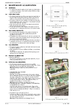
- Mount the cable lugs directly on the DC output strips
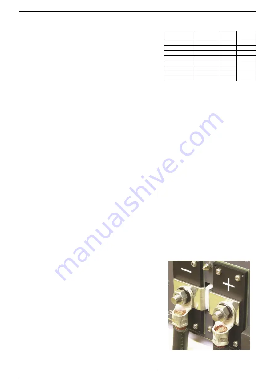
followed by a washer, split washer and a nut (see fig. 4 - 1).
Always in this order!
- Never place washers between the lugs and the strips
because this can result in excessive heat!
- Only use nuts and washers supplied with the unit.
Switch on unit.
Disable the Keylock function, see next paragraph.
Check the unit is not in Remote CV or Remote CC (LED’s for
this function should be off). Press the REMOTE/LOCAL
button until both LED’s are off.
Turn on DC output by pressing the OUTPUT ON/OFF button.
Turn both the CV and CC potentiometer a few turns
clockwise.
A voltage should now be present on the output.
By pressing the DISPLAY CV/CC SETTING button the meters
fig 4 - 1
Low resistive cable connection by mounting the
cables directly on the DC output strips.
Unit
DC Output
cable [mm
2
]
Bolts
Torque
[Nm]
SM15-400
150
M12
80
SM30-200
70
M10
40
SM45-140
35
M10
40
SM60-100
35
M10
40
SM70-90
25
M10
40
SM120-50
10
M8
20
SM300-20
4
M8
20
SM600-10
2.5
M8
20
table 4 -1
Recommended cable diameters and mounting torque.


