INSTALLATION
SM6000
14 / 21
DELTA ELEKTRONIKA B.V.
rev. Nov. 2020
will show the setting of the CV and CC potentiometer.
By pressing the DISPLAY LIMITS button the voltmeter will
show the setting of the CV-limit and the CC-limit
potentiometer.
Check that the cooling of the unit is not obstructed.
4.5
KEYLOCK
If the function KEYLOCK is activated, it is no longer possible
to operate the REMOTE/LOCAL button and the OUTPUT
ON/OFF button. This function can be useful to protect the
output from accidental shutdown. The function KEYLOCK
does not influence the operating of the CV, CC, CV-limit and
CC-limit potentiometers.
Units with digital encoders:
For SM300-20 / SM600-10 and units with Option P220, also
the digital encoders for CV and CC are disabled with the
Keylock function. This means settings of the voltage and
current do not change when the encoders are operated. It is
still possible to operate the analog CV-limit and CC-limit
potentiometers.
Activate Keylock:
Pressing the buttons DISPLAY SETTINGS and DISPLAY
LIMITS at the same time for more than 3 seconds, activates
the function KEYLOCK. The moment this function is
activated, the LED’s for REMOTE CV / CC and for OUTPUT
ON will blink a few times.
Disable Keylock:
Pressing the same buttons again for 3 seconds, disables the
Keylock function. The
LED’s for REMOTE CV / CC and for
OUTPUT ON will blink again to indicate the new setting.
4.6
SELECT START-UP MODE
The below is only applicable for SM300-20 / SM600-10 and
units with magnetic encoders - option P220:
-
Setting switch SW1-5 at the rear panel in position DOWN,
the unit will always start at 0V / 0A after mains switch on.
- Setting switch SW1-5 in position UP, the settings after mains
switch on will be the same as before switching the mains
voltage off.
4.7
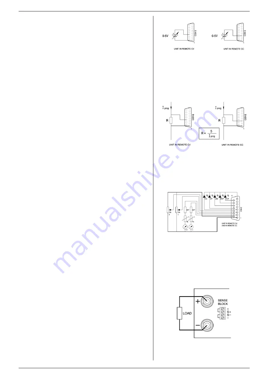
ANALOG PROGRAMMING
Set DIP switch 1 of SW1 in position UP to select CON E for
programming. For SM300-20 / SM600-10 see paragraph ISO-
AMP.
Disable Keylock.
Set the unit in REMOTE CV for voltage programming and/or
in REMOTE CC for current programming.
Use the REMOTE/LOCAL button and push this button several
times until the right setting is activated.
Note that pushing the REMOTE/LOCAL button will shutdown
the output to avoid accidental damage to the load.
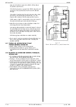
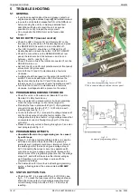
Connect the programming voltage source(s) (0 - 5 V) to the
analog programming connector CON E on the rear panel (see
fig. 4 - 2 and fig. 4 - 3). Always use a
shielded cable
(max.
30 meter) for programming.
Turn the output on again with the OUTPUT ON/OFF button.
If only the voltage is programmed, the maximum current can
still be set with the CC knob on the front panel and vice versa.
If this is not desirable the unit can be ordered with Option
P001 or Option P220 in order to have a fixed setting for the
CV and the CC knob on the front panel, see also paragraph
34) in previous chapter "General".
To avoid hum or noise, the programming cable may have to
be twisted in some cases.
To program the unit by current instead of voltage, simply use
a parallel resistor as a current to voltage converter.
Pressing the DISPLAY SETTINGS button will show the
programmed values for CV and CC.
Warning:
The analog inputs are not isolated from the output.
The Ø of the prog. input (pin 1) is internally connected to the
S
–, the S– is connected to the negative output. To protect the
internal wiring a 650 mA self-resetting fuse is connected in
fig 4 - 2
Programming by voltage:
left voltage -, right current programming.
fig 4 - 3
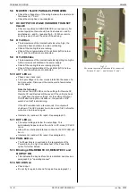
Programming by current:
left voltage -, right current programming.
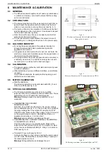
fig 4 - 4
Remote control.
fig 4 - 5
Local sensing.


