background image

INSTALLATION 


SM6000 

16 / 21 

DELTA ELEKTRONIKA B.V. 

rev. Nov. 2020 


4.13


BATTERY CHARGER 


The CV / CC regulated power supplies are ideal battery 
chargers. Once the output is set at the correct voltage the 
battery will charge constantly without overcharging. This can 
be useful for emergency power systems. 


Protective measures


Use a CIRCUIT BREAKER in series in order to protect the 
power supply from 

accidental reverse connection

 (see fig. 4 

- 8).The circuit breaker should have a DC voltage rating twice 
the battery voltage. Use the very fast type (Z), a type meant 
for protecting semiconductors (see table 4 - 2). 


The unit has a reverse diode in parallel with the DC output, 
this diode and the wiring cannot withstand the thousands of 
amperes supplied by a wrongly connected battery. 

4.14


REMOTE SHUTDOWN 


The Remote ShutDown can be operated on CON E by a 
voltage of +4 V...+12 V or by a relay contact between Vref 
and Remote ShutDown (pin 9 and 5) (see fig. 4 - 9). 


When the unit is programmed with an optional PSC, a 
software command can be used for Remote Shutdown. 


In the Remote ShutDown condition, the RSD LED will be on. 
The DCF LED, DCF status and the DCF relay will be off. 
 

Important:

 If the link from the Interlock connector (CON A) 

has been removed, the RSD LED will be on, but in this  
condition also the DCF LED, the DCF status and the DCF 
relay will be on.  

4.15


MASTER / SLAVE SERIES OPERATION 


Connect output terminals and test system in 

normal series


operation. Ensure that all DC power connections are reliable.  


The voltage drop in the connecting leads between the units 
should be kept < 10 mV. 


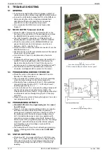
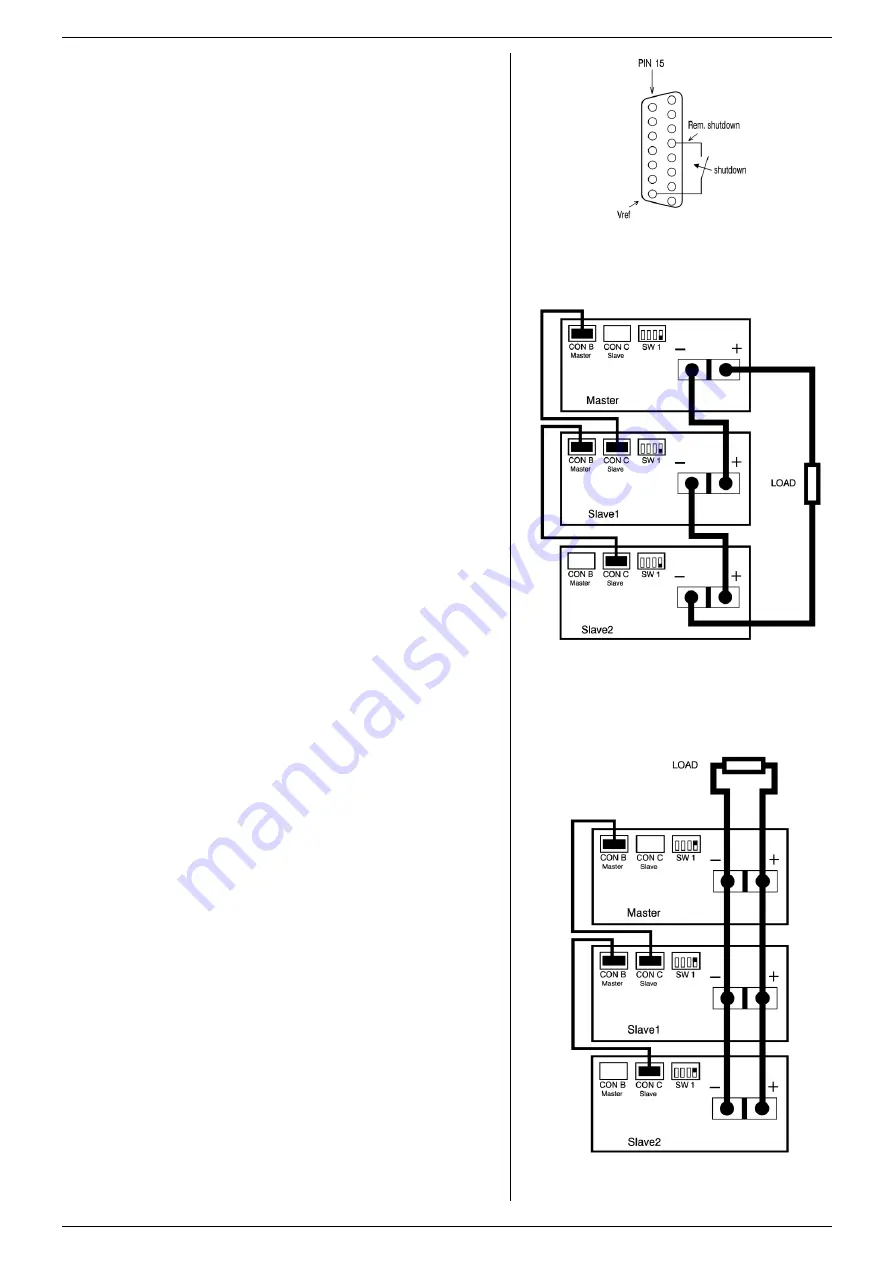
Switch off all units. Connect units as shown in fig. 4 - 10.  
To connect the slaves with the master via CON B and CON 
C, use standard UTP cables (RJ45).  
On all units put DIP switch 4 of SW1 in position DOWN to set 
the units in M/S series mode.  


After turning the units on again, the slaves will be in Remote 
CV mode and the Keylock (see previous paragraph  is 
activated. This is because the unit automatically detects the 
presence of the RJ45 connector in CON C (if this cable is 
connected to another unit). 
 

If the RJ45 connector is removed from CON C when the unit 
is turned on, the DC output will shutdown to avoid  accidental 
damage.  
If the cable is inserted when the unit is turned on, the DC 
output shuts down, the unit changes to Remote CV /  CC, the 
Keylock will be activated and the output will turn back on.  
If DIP switch 4 of SW1 is operated when the unit is turned on, 
the DC output will shutdown to avoid accidental damage. 


The maximum number of slaves is only limited by the 
maximum total voltage of 600 V. 

4.16


MASTER / SLAVE PARALLEL OPERATION 


Note: Master / Slave parallel is not recommended for 
more than 3 units, consult factory for using more than 3 
power supplies in parallel. 


First connect the DC power terminals and test system in 

normal parallel

 operation. Ensure that all power connections 

are reliable.  


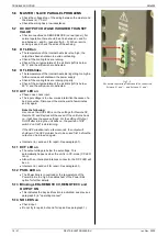
Second, switch off all units. To connect the slaves with the 
master via CON B and CON C, use standard RJ45 
connectors according to fig. 4 - 11.    
On all units put DIP switch 4 of SW1 in position UP to set the 
units in M/S parallel mode. In this mode the DCF LED, DCF 
relay and DCF status on the slaves are disabled because the 
slaves are always in CC mode. 


After turning the units on again, the slaves will be in Remote 
CC mode and the Keylock (see previous paragraph 5)  is 
activated. This is because the unit automatically detects the 


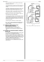
fig 4 - 9 

Remote Shutdown with switch. 


fig 4 – 10 

Master / Slave series connections. 


fig 4 - 11 

Master / Slave parallel connections. 


Summary of Contents for SM 120-50

Page 1: ...50 SM300 20 SM600 10 PRODUCT MANUAL Contents 1 Safety Instructions 2 Sicherheitshinweise 3 General 4 Installation 5 Trouble Shooting 6 Maintenance Calibration 7 EU Declaration of Conformity Product Manuals and Driver Example Software For several Applications build in Options and Interfaces there are Application Notes separate Product Manuals and Driver Example Software available on available on ou...

Page 2: ...red safe DC power terminals and sense connections programming monitor status signals Interlock Master Slave connections ACF DCF relay all Delta Elektronika interfaces Caution 1 If a low voltage unit has both DC power terminals floating or if the DC terminals are in series with an external high AC or DC voltage the minus DC power terminal can exceed the safe value in respect to ground as specified ...

Page 3: ...ch off the unit Disconnect the unit from the AC mains supply and from the DC power application Wait for 5 minutes to allow internal capacitors to discharge Unscrew the screws and remove the cover s Always place the cover s back before connecting the unit to the mains supply again 1 12 Environmental Conditions The Delta Elektronika power supplies safety approval applies to the following operating c...

Page 4: ...rammierung Monitor Status Signale InterLock Master Slave Anschlüsse ACF DCF Relais Schnittstellen mit Funktionale Isolation Schnittstellen ohne Sicherheitsisolation Vorsicht 1 Falls beide DC Anschlussklemmen eines Niederspannungsgerätes potentialfrei sind oder falls die DC Klemmen in Reihe mit einer externen AC oder DC Hochspannung geschaltet sind kann die minus DC Anschlussklemme den sicheren Wer...

Page 5: ...ungsbedingungen Die Stromversorgungssicherheitszulassung von Delta Elektronika gilt für die folgenden Betriebsbedingungen Innengebrauch Umgebungstemperatur 20 bis 50 C Maximale relative Luftfeuchtigkeit 95 nicht kondensierend bis zu 40 C 75 nicht kondensierend bis zu 50 C Höhe bis zu 2000 m Verschmutzungsgrad 2 Diese Kennzeichnung auf dem Produkt seiner Verpackung oder seiner Literatur weist darau...

Page 6: ...and the harmonic distortion of the AC input current will be relatively low The peak inrush current is electronically limited Switching on and off repeatedly will not result in excessive currents like with NTC circuits 3 4 STANDBY AC INPUT POWER The unit consumes very little power when in standby This makes it possible to leave the AC input power on when the output is disabled using the Output On O...

Page 7: ... by the computer 3 12 MONITORING OUTPUTS The monitor outputs give a voltage 0 5 V proportional to the output current or voltage The output current can easily be measured using the I monitor see fig 3 6 The monitor outputs are buffered with op amp s and protected with series resistors and parallel zener diodes see fig 3 7 The table in fig 3 5 shows the impedance levels of the monitoring outputs For...

Page 8: ...to the ACF relay see fig 3 10 fig 3 10 Status relay outputs on CON D This situation gives the relay positions during fault condition fig 3 8 Location of output terminals and analog programming connector on the rear panel CON A Interlock Connector CON B Master connector for Master Slave operation output CON C Slave connector for Master Slave operation input CON D Relay Outputs contacts 1 6 CON E An...

Page 9: ... the rise and fall time is 5 to 25 times faster see datasheet The programming source must be floating or otherwise an ISO AMP CARD must be used a non floating source will result in slope distortion When using hi speed programming it is generally not recommended to use remote sensing or serial parallel operation Consult factory for advice Note that the output ripple is higher 3 20 PULSATING LOAD To...

Page 10: ...ld up time see fig 3 17 3 26 TURN ON DELAY The DC output voltage is available about 0 2 sec after mains switch on 3 27 AC INRUSH CURRENT The inrush current is electronically limited Repeatedly switching on and off does not change the maximum peak current Switching on and off at a fast rate can overheat the inrush current limiter With the result that the unit does not start anymore After cooling do...

Page 11: ...llel operation in combination with Power Sink option only one unit can have a Power Sink Refer to Power Sink manual for details and restrictions 3 32 MASTER SLAVE OPERATION The Master Slave feature makes it possible to use power supplies as building blocks to form one large unit fig 3 20 Mixed parallel series operation is also possible to a maximum of 600 V The resulting combination of units behav...

Page 12: ...ons such as variable coarse fine pitch adjustment locking of CV CC settings and a selectable start up voltage start at 0V 0A or at last settings The lower voltage units have analog potentiometers for the CV CC controls Optional they can be equipped with screwdriver adjustment for CV CC settings at the front panel or also with digital encoders option P220 See fig 3 23 for option P001 3 35 COOLING T...

Page 13: ...ts is allowed without limitations See previous paragraph for cooling instructions 4 4 OPERATING THE UNIT FOR THE FIRST TIME Check there is no condensation on the unit If there is allow some time to dry Check there is a link between and S and between and S on the SENSE BLOCK on rear panel Check there is a link between pins of the Interlock CON A Set the CV and CC potentiometers to minimum fully ant...

Page 14: ...ion UP the settings after mains switch on will be the same as before switching the mains voltage off 4 7 ANALOG PROGRAMMING Set DIP switch 1 of SW1 in position UP to select CON E for programming For SM300 20 SM600 10 see paragraph ISO AMP Disable Keylock Set the unit in REMOTE CV for voltage programming and or in REMOTE CC for current programming Use the REMOTE LOCAL button and push this button se...

Page 15: ...o S and S See fig 4 5 and fig 4 6 With remote sensing the voltage on the load can be kept constant The voltage drop in the load leads will be compensated This feature is not recommended for normal use because it can easily give problems Max 2 V per load lead can be compensated Note that the voltage drop in the leads decreases the max output voltage rating In fig 4 7 it can be seen that on a 15 V p...

Page 16: ...aster via CON B and CON C use standard UTP cables RJ45 On all units put DIP switch 4 of SW1 in position DOWN to set the units in M S series mode After turning the units on again the slaves will be in Remote CV mode and the Keylock see previous paragraph is activated This is because the unit automatically detects the presence of the RJ45 connector in CON C if this cable is connected to another unit...

Page 17: ...o each other to have a low inductance Not following these instructions can cause instability The S and S could be connected to the load if desired but this is not recommended because of the complexity and possible instability 4 17 PARALLEL OPERATION OF FAST PROGRAMMING VERSIONS Master Slave operation is not recommended Normal parallel operation can give problems each combination has to be tested f...

Page 18: ...emote CV and or Remote CC LED should be on The unit works OK in manual control but in programming mode the output voltage current has a large error Probably the fuse in series with Ø pin 1 of programming connector tripped the fuse F27_1 650 mA is a self resetting type see fig 5 1 To check the fuse F27_1 measure the voltage between Ø and the minus output during the fault condition The voltage shoul...

Page 19: ... because of a bad connection Disconnect the mains wait a few minutes and try again Note the following As soon as the ACF LED is on the settings for Remote CV Remote CC and Keylock will be saved If the unit turns back on it will have the same settings For the setting of Output On Off after turning the unit back on the position of DIP switch 2 on SW1 is determining If the ACF situation lasts a few s...

Page 20: ...brated and normally need no further calibration After installation of a new or different interface no calibration is needed Only in special situations for example after repairing a unit calibration can be necessary 6 5 METER CALIBRATION DIGITAL METERS The full scale indication can be calibrated with R25_31 and R25_36 on P596 see fig 6 2 6 6 SPECIAL CALIBRATIONS The following calibrations must be d...

Page 21: ...e official Journal of the European Communities EN 61000 6 3 2007 Generic Emissions residential light industrial A1 2011 EN 61000 3 2 2014 Power Harmonics EN 61000 3 3 2013 Voltage fluctuation and flicker EN 61000 6 1 2007 Generic Immunity residential light industrial EN 61000 6 2 2005 Generic Immunity industrial environment EN 60950 1 2006 Safety of IT equipment A1 2010 A11 2009 A12 2011 A2 2013 E...

Reviews: